EasyManua.ls Logo

Panasonic TC-P60ST60 - User Manual

Panasonic TC-P60ST60
68 pages
To Next Page IconTo Next Page
Loading...
© Panasonic Corporation 2013 Unauthorized copy-
ing and distribution is a violation of law.
ORDER NO. MTNC130339CE
B34 Canada: B62
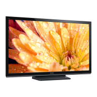
60 Inch Class 1080p Plasma HDTV
Model No. TC-P60ST60
GPF16DU Chassis
For detailed troubleshooting information and circuit explanations,
refer to the "QSM/Service Hints/Troubleshooting Information(TI)" and Seminar/Training Manual/Technical
Guide(TG) documents posted on the TSN web site.
For information about this model, type TC-P2013 in the model box under "Direct Search".
Question and Answer IconNeed help?

Do you have a question about the Panasonic TC-P60ST60 and is the answer not in the manual?

Panasonic TC-P60ST60 Specifications

General IconGeneral
BrandPanasonic
ModelTC-P60ST60
CategoryPlasma TV
LanguageEnglish

Summary

Safety Precautions and Guidelines

Safety Checks and Guidelines

Guidelines for repairs, handling components, and leakage current checks.

Warning

Electrostatic Discharge (ESD) Prevention

Techniques to prevent ESD damage to sensitive components.

Lead Free Solder (PbF) Information

Service Navigation

PCB Layout and Functions

Diagram and list of PCB board names and their functions.

Specifications

Technical Descriptions

KEY Specification for Protected Content

Details on KEY data generation, protected content, and IC replacement.

Service Mode Operations

Contents of Adjustment Mode

Option - Mirror Function

Service Tool Mode Operations

Hotel Mode Operations

USB Data Copy Operations

TV to USB Data Copy Procedure

USB to TV Data Copy Procedure

Troubleshooting Guide

Service Fixtures and Tools

SC Jig Usage

Purpose and usage of the SC jig for failure diagnosis.

Disassembly and Assembly Instructions

Disassembly Flow Chart

Visual chart outlining the unit's disassembly sequence.

Disassembly Procedures

Pedestal Removal

Steps to remove the TV pedestal.

Bottom Cover Removal

Steps to remove the bottom cover.

AC Cord Clamper B Removal

Steps to remove the AC cord clamper B.

WiFi Dongle Removal

Steps to remove the WiFi dongle.

Bluetooth Module Removal

Steps to remove the Bluetooth module.

Back Cover Removal

A-Panel Removal

P-Panel Removal

K-Panel Removal

SS-Panel Removal

SS2-Panel Removal

Multi-Button Switch Units Removal

SU-Panel Removal

SD-Panel Removal

SC-Panel Removal

AC-Inlet Removal

M8 Nut Metals Removal

Speaker Slim SQs Removal

Woofer Middle Removal

USB Cable (A-WiFi) Removal

Metal Bracket Bottom Removal

Cabinet Removal

Contact Metals Removal

C1-Panel Removal

C2-Panel Removal

C3-Panel Removal

Plasma Panel Replacement

EMI Processing

Measurements and Adjustments

Adjustment Operations

General information on adjustments.

Vsus Selection Procedure

Procedure for setting Vsus voltage after panel replacement.

White Balance Adjustment

Block Diagrams

Main Block Diagram

Overall system block diagram of the TV's main functions.

Block Diagram (1;4)

Block Diagram (2;4)

Block Diagram (3;4)

Block Diagram (4;4)

Wiring Connection Diagrams

Wiring Caution Statement

Important cautions for flexible cable assembly and locking.

Wiring Connections (1)

Wiring connections diagram for specific connectors and cables.
Wiring Connections (2)

Wiring Connections (3)

Wiring Connections (4)

Wiring Connections (5)

Wiring Connections (6)

Wiring Connections (7)

Wiring Connections (8)

Wiring Connections (9)

Wiring Connections (10)

Exploded View 1

Exploded View 2

Included Accessories

Related product manuals