TH-40A400X
23
8 Measurements and Adjustments
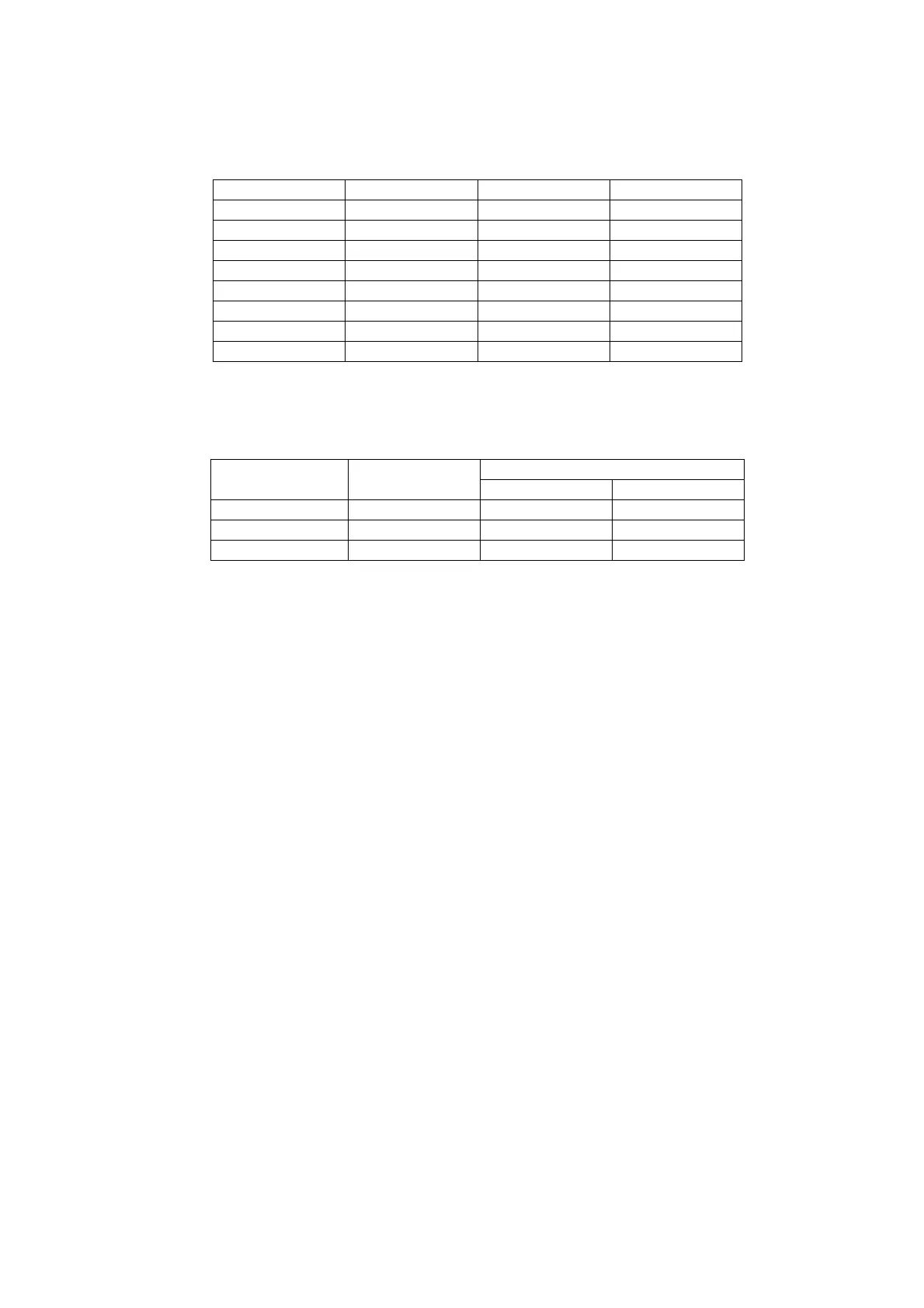
8.1. Voltage chart of A-board
Set A-Board to a dummy set and check the satisfaction with the specified voltage as following table.
8.2. Voltage chart of P-board
Set P-Board to a dummy load and check the satisfaction with the specified voltage as following table.
Power Supply Name Measurement Point Specification (V) Remark
TNR1.8V TP8705 1.74 - 1.90 -
VCCK1.1V TP8700 1.14 ~ 1.28 -
SUB3.3V TP8711 3.19 - 3.46 -
SUB5V TP8702 4.9 - 5.2 -
PNL12V TP8300 11.5 - 12.5 -
DDR1.8V TP8707 1.75 ~ 1.85V -
STB3.3V TP8708 3.2V ~ 3.40V -
TNR3.3V TP6701 3.2V ~ 3.4V -
Voltage Test Point
Specification
Operate STBY
5.3V TP7507 5.2 ± 0.2V 5.2 ± 0.2V
16V TP7508 15.8 ± 0.5V -
24V TP7511 24.0 ± 2.4V -
NOTE: GND REFERENCE TP7520/ TP7521/ TP7522 (COLD SIDE)
Step 1 Supply AC 100V/230 to JK7101 connector in the P-Board. Main power button is OFF.
Step 2 Supply DC 2.5V to TV_SUB_ON P2 connector - pin 8 (TP7416), displayed as SWITCH.
NOTE : GND REFERENCE TP7413/TP7414/TP7415/TP7515/TP7516/TP7517 (COLD SIDE)