26
TH-42LFP30W / TH-47LFP30W
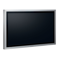
5. Undo the screws (Model 47V: 1; Model 42V: 2), then
remove the thermal conductivity plate from the side of the
LCD panel. (SCR FLT 4X6)
• Thermal conductivity sheets are attached to the front and
back sides of the thermal conductivity plate.
6. Remove the LVDS cable and inverter cable from the LCD
panel.
7. Replace it with the replacement LCD panel.
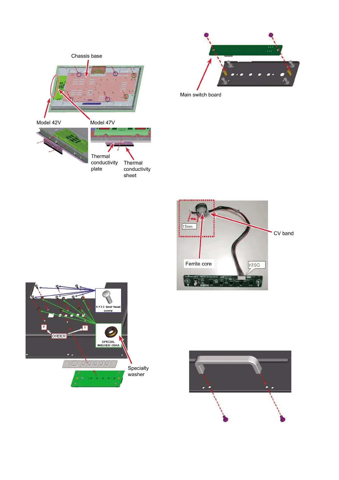
8.16. Replacing the main switch
board
1. Undo the 6 screws to take off the control button and main
switch board together with the metal holder fitting from
the back plate. (SPECIAL SCREW 4X12)
2. Undo the 2 screws to remove the main switch board from
the metal holder fitting. (SCR PAN+SW+W 3X10)
Precautions for removing and fitting the main switch
board.
• 6 specialty washers for ensuring dustproof and waterproof
performance are fitted on 6 screws. When fitting the main
switch board, always put the 6 specialty washers on screws
facing the correct direction (rubber side is facing to the back
plate).
8.17. Fitting the core for the main
switch board cable
When replacing the main switch board cable, place the ferrite
core 15 mm from the coupler K39G on the main board and wind
the cable once on to it and secure it with CV band.
8.18. Removing the handles
Take the following steps to change the handles when replacing
the back plate, etc.
1. Undo the 8 screws to remove the 4 handles from the back
plate. (SPECIAL SCREW 5X10)
2. Fix the handles onto the replacement back plate.
 Loading...