TH-L32X50D
13
6.2. Power LED Blinking timing chart
1. Subject
Information of LED Flashing timing chart.
2. Contents
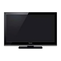
When an abnormality occurs, the protection circuit will operate and reset the unit to stand by mode. During this time, the
defective block can be identified by the number of blinking times of the Power LED on the front panel of the unit as follow:
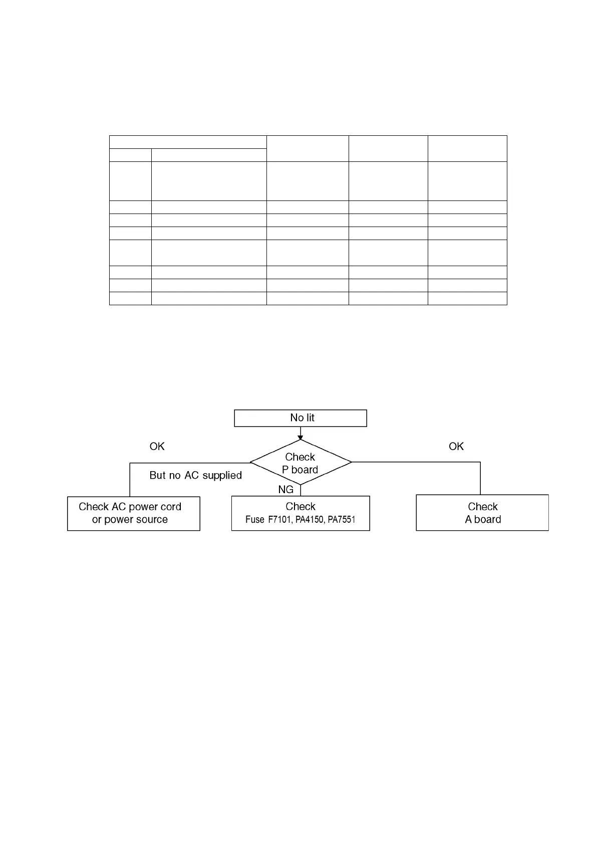
6.3. No Power
First check point
There are following 2 states of No Power indication by power LED.
1. No lit
2. Red is lit then turns red blinking a few seconds later. (See 6.2.)
LCD
Remark
EEPROM ADR
address
PCB NAME
Times SOS
1 BackLight_SOS 0 × 0461
A-Board
P-Board
LCD Panel
3 SOS(Tuner_SOS) 0 × 045B A-Board
4 SUB12V_SENSE_SOS 0 × 045A A-Board
7 SUB3.3V_SENSE_SOS 0 × 0459 A-Board
9 SOUND_SOS 0 × 045D
A-Board
P-Board
12 BackEnd(sLD)_SOS 0 × 0466 A-Board
13 EMERGENCY_SOS communication error A-Board
14 IROM_SOS Error of STM micon A-Board

 Loading...