TH-L42E6S
26
8 Measurements and Adjustments
8.1. Voltage chart of A-board
Set A-Board to a dummy set and check the satisfaction with the specified voltage as following table.
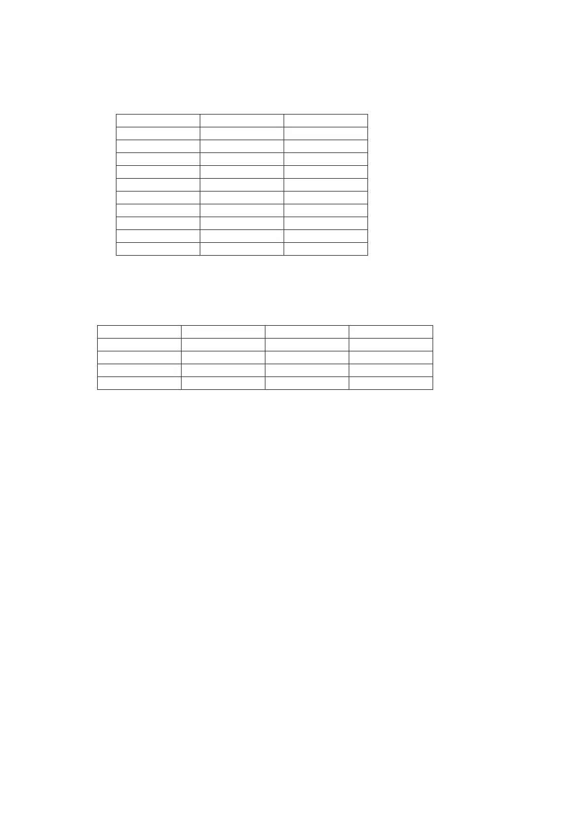
8.2. Voltage chart of P-board
Set P-Board to a dummy load and check the satisfaction with the specified voltage as following table.
Power Supply Name Measurement Point Specification
PANEL12V TP4000 / 4001 11.50V - 12.50V
SUB5V TP5420 4.95V - 5.40V
SUB3.3V TP5400 3.17V - 3.43V
SUB1.8V TP8714 1.70V - 1.90V Only TNPH1038
SUB1.5V TP8100 1.435V - 1.585V
SUB1.2V TP8101 1.140V - 1.260V
LNB_PWR TP6702 15.30V - 17.10V Only JPN_Model
JP_TU_2.5V TP5705 2.38V - 2.62V
DMD_1.2/1.1V TP5702 1.14V - 1.26V Only JPN_Model
DMD_1.2/1.1V TP5703 1.14V - 1.26V Only DTMB_Model
Output Test Point Step 1 Step 2
24V TP7407 < 1V 24 ± 1.2V
16V TP7410 < 1V 15.7 ± 0.6V
5VS TP7501 5.3 ± 0.2V 5.3 ± 0.2 V
PFC TP7201 or TP7202 < 340V 390V ± 15V *HOT