34
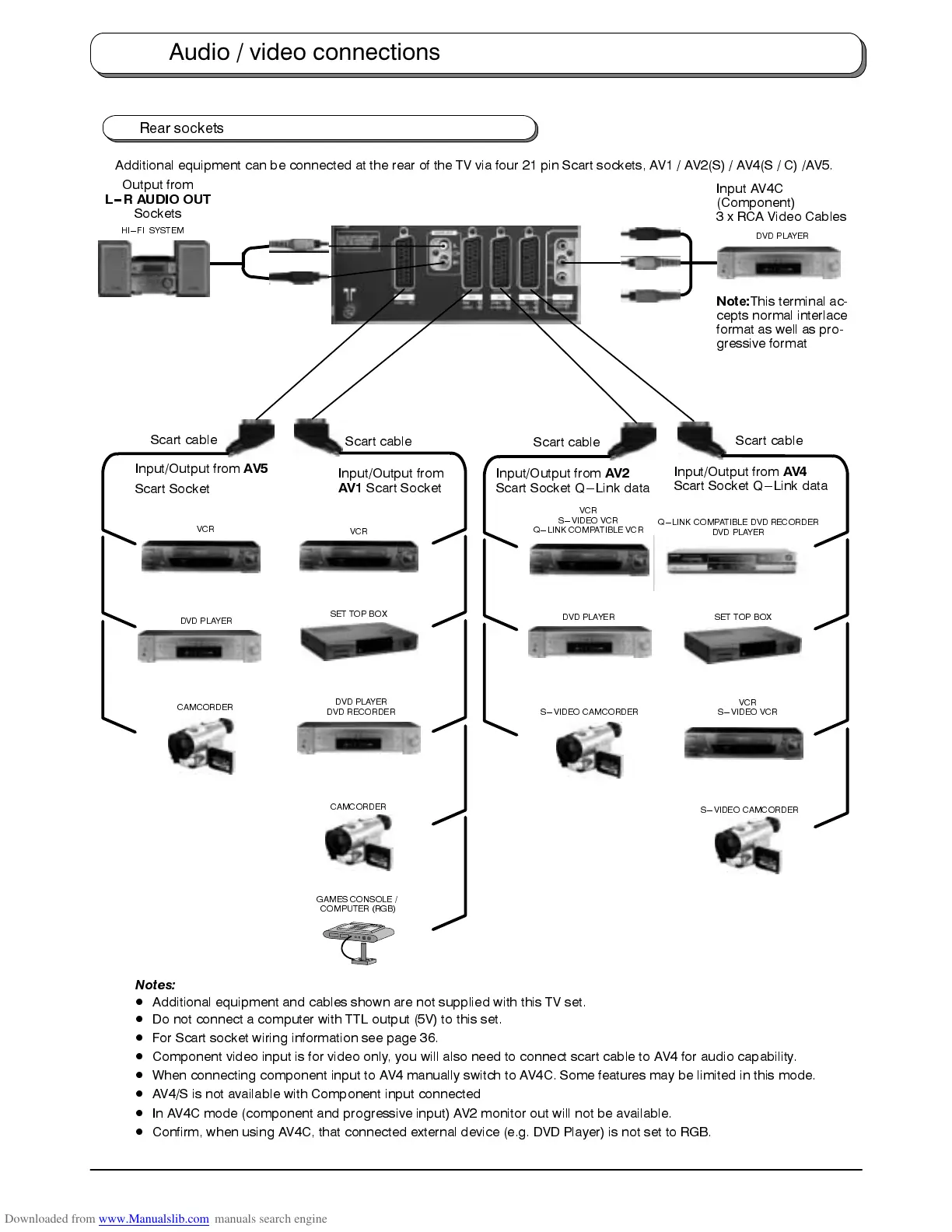
Rear sockets
Additional equipment can be connected at the rear of the TV via four 21 pin Scart sockets, AV1 / AV2(S) / AV4(S / C) /AV5.
DVD PLAYER
DVD RECORDER
Input/Output from
AV1
Scart Socket
VCR
S---VIDEO VCR
Q---LINK COMPATIBLE VCR
Scart cable
Scart cable
VCR
GAMES CONSOLE /
COMPUTER (RGB)
SET TOP BOX
Input/Output from
AV4
Scart Socket Q---Link data
Scart cable
VCR
S---VIDEO VCR
CAMCORDER
S---VIDEO CAMCORDER
SET TOP BOX
S---VIDEO CAMCORDER
DVD PLAYER
Input AV4C
(Component)
3 x RCA Video Cables
Note:
This terminal ac-
cepts normal interlace
format as well as pro-
gressive format
DVD PLAYER
Input/Output from
AV5
Scart Socket
VCR
Scart cable
CAMCORDER
DVD PLAYER
Input/Output from
AV2
Scart Socket Q---Link data
Q---LINK COMPATIBLE DVD RECORDER
DVD PLAYER
HI---FI SYSTEM
Output from
L--R AUDIO OUT
Sockets
Notes:
D
Additional equipment and cables shown are not supplied with this TV set.
D
Do not connect a computer with TTL output (5V) to this set.
D
For Scart socket wiring information see page 36.
D
Component video input is for video only, you will also need to connect scart cable to AV4 for audio capability.
D
When connecting component input to AV4 manually switch to AV4C. Some features may be limited in this mode.
D
AV4/S is not available with Component input connected
D
In AV4C mode (component and progressive input) AV2 monitor out will not be available.
D
Confirm, when using AV4C, that connected external device (e.g. DVD Player) is not set to RGB.
Audio / video connections