9 Disassembly and Assembly Instructions
9.1. Remove the Rear cover
1. See PCB Layout (Section 3)
9.2. Remove the AC inlet
Caution:
To remove P.C.B. wait 1 minute after power was off for dis
charge from electrolysis capacitors.
1. Unlock the cable clampers to free the cable.
2. Disconnect the connector (P9).
3. Remove the screw (x1 and remove the AC inlet.
9.3. Remove the P-Board
Caution:
To remove P.C.B. wait 1 minute after power was off for dis
charge from electrolysis capacitors.
1. Unlock the cable clampers to free the cable.
2. Disconnect the connectors (P2, P6, P7, P9, P11 and
P35).
3. Remove the screws (x9 and remove the P-Board.
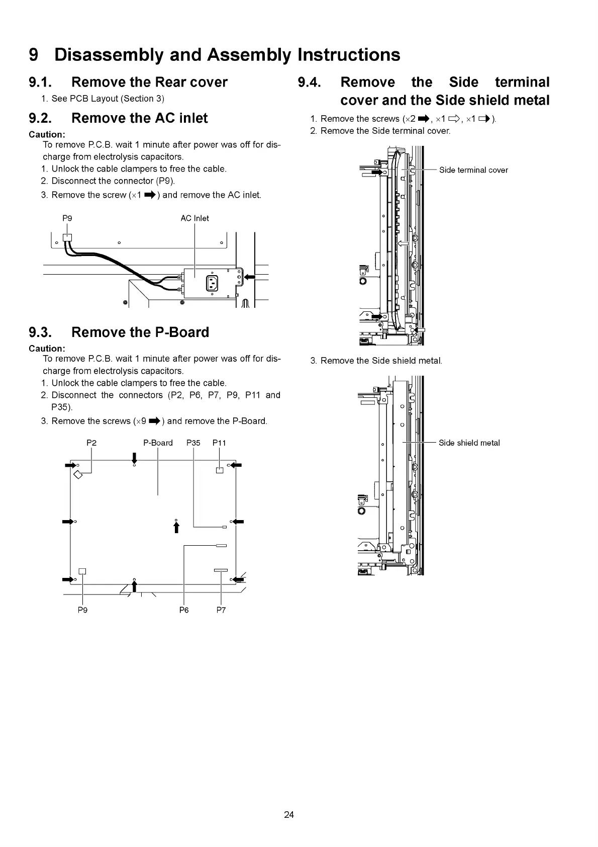
9.4. Remove the Side terminal
cover and the Side shield metal
1. Remove the screws (x2 x1 cz|>, х1 сф).
2. Remove the Side terminal cover.
3. Remove the Side shield metal.
24