Do you have a question about the Panasonic TX-P42C2B and is the answer not in the manual?
General guidelines for conducting repairs and servicing safely, including wiring and connector handling.
Procedure for checking touch currents to prevent shock hazards using a measuring network.
Techniques to reduce component damage from static electricity.
Details on KEY data generation, replacement procedures for ICs, and model-specific key information.
Instructions for accessing the service mode menu and using key commands for navigation.
Accessing and using the service tool mode for diagnostics and SOS history display.
Methods to access and interpret the IIC bus line check results and identify check points.
Chart correlating LED blink patterns to specific fault conditions for diagnostics.
Troubleshooting steps for scenarios where the unit does not power on based on LED status.
Troubleshooting guide for issues related to the absence of a picture, checking signal paths.
Identifying possible PCB defects related to local screen failures on the plasma display.
Detailed instructions for replacing the plasma panel assembly, including handling precautions.
Procedure for setting the Vsus voltage to LOW or HIGH after panel or A-board replacement.
Explains symbols, references, and general notes used in schematic diagrams for accurate interpretation.
Detailed schematic for the Power Supply (P-Board), part 1 of 4, showing AC input and PFC circuits.
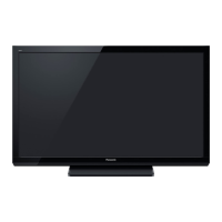
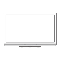
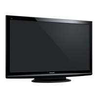
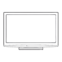
Visual exploded views and list of mechanical replacement parts for the TV.
Comprehensive list of electrical components for replacement, including part numbers and specifications.