1 Safety Precautions
1.1. General Guidelines
1. When servicing, observe the original lead dress. If a short circuit is found, replace all parts which have been overheated or
damaged by the short circuit.
2. After servicing, see to it that all the protective devices such as insulation barriers, insulation papers shields are properly
installed.
3. After servicing, make the following leakage current checks to prevent the customer from being exposed to shock hazards.
4. When servicing, observe the original lead dress. If a short circuit is found, replace all parts which have been overheated or
damaged by the short circuit.
5. After servicing, see to it that all the protective devices such as insulation barriers, insulation papers shields are properly
installed.
6. After servicing, make the following leakage current checks to prevent the customer from being exposed to shock hazards.
1.2. Touch-Current Check
1. Plug the AC cord directly into the AC outlet. Do not use an isolation transformer for this check.
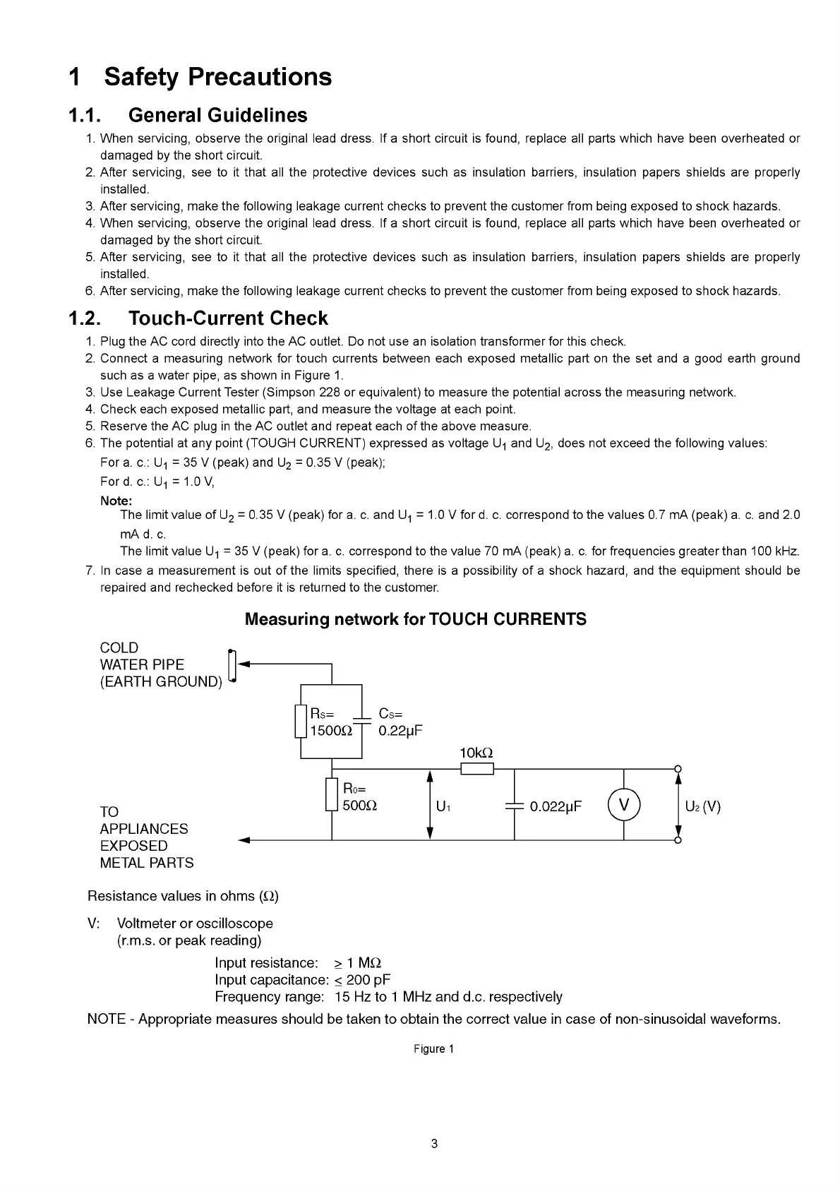
2. Connect a measuring network for touch currents between each exposed metallic part on the set and a good earth ground
such as a water pipe, as shown in Figure 1.
3. Use Leakage Current Tester (Simpson 228 or equivalent) to measure the potential across the measuring network.
4. Check each exposed metallic part, and measure the voltage at each point.
5. Reserve the AC plug in the AC outlet and repeat each of the above measure.
6. The potential at any point (TOUGH CURRENT) expressed as voltage U1 and U2 , does not exceed the following values:
For a. c.: U1 = 35 V (peak) and U2 = 0.35 V (peak);
For d. c.: U1 = 1.0 V,
Note:
The limit value of U2 = 0.35 V (peak) for a. c. and U1 = 1.0 V for d. c. correspond to the values 0.7 mA (peak) a. c. and 2.0
mA d. c.
The limit value U1 = 35 V (peak) for a. c. correspond to the value 70 mA (peak) a. c. for frequencies greater than 100 kHz.
7. In case a measurement is out of the limits specified, there is a possibility of a shock hazard, and the equipment should be
repaired and rechecked before it is returned to the customer.
Measuring network for TOUCH CURRENTS
COLD
WATER PIPE
(EARTH GROUND)
Rs=
1500Q
_L Cs=
0.22|jF
10kQ
-1
k 1
-------
1
Ro=
----------------
J
500Q
'
U1 =
r
= 0.022|jF (V)
J Q L jJ J U U i i U 1 — |— и . и ^ г ф Г ^ V J | U2 (V)
APPLIANCES
EXPOSED
METAL PARTS
Resistance values in ohms (Q)
V: Voltmeter or oscilloscope
(r.m.s. or peak reading)
Input resistance: > 1 MQ
Input capacitance: < 200 pF
Frequency range: 15 Hz to 1 MHz and d.c. respectively
NOTE - Appropriate measures should be taken to obtain the correct value in case of non-sinusoidal waveforms.
Figure 1
3