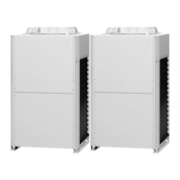
Do you have a question about the Panasonic U-8MF2E8 and is the answer not in the manual?
| Brand | Panasonic |
|---|---|
| Model | U-8MF2E8 |
| Category | Air Conditioner |
| Language | English |
Crucial safety information covering wiring, transportation, and installation procedures.
Guidelines for handling refrigerant tubing, preventing contamination, and ensuring proper connections.
Safety measures to follow during maintenance and servicing of the unit.
Standards for minimum room volume to ensure safe refrigerant density levels.
Requirements for minimum indoor floor space related to refrigerant density limits.
Instructions on processing tubing, preventing impurities, and proper bending techniques.
Guidelines for recharging refrigerant in liquid form and handling gas leaks.
Lists specific tools required for R410A refrigerant systems, noting incompatibilities.
Information on filling refrigerant charge labels and compliance with Kyoto Protocol.
Overview of the 3WAY System, its components, and required test run settings.
Rules for operating multiple outdoor units, including delayed start and stop procedures.
Details on compressor types, selection rules, operating modes, start/stop, frequency range, and forced stop.
Adjusting heat exchanger capacity for condenser and evaporator modes.
Manages discharge temp, low pressure, and over-current protection for compressors.
Control of DCV, SCV, and PBV for heat exchanger mode and capacity.
Control of SC circuit valve (MOV4) and crankcase heaters (CH1, CH2).
Details on fan modes, maximum/minimum values, and forced modes for different unit types.
Configuration for high static pressure operation in outdoor units.
Controls fan operation to prevent snow accumulation on stopped fans.
Settings for reducing noise by adjusting fan speed and capacity.
Fixed initial fan mode and operation after initial mode for cooling and heating.
Control of MOV for each indoor unit operation mode (stop, fan, cooling, heating).
Control of solenoid valve kit for switching indoor unit modes and special operations.
CCU intervenes in indoor unit fan control based on operating mode and priority, including dry and heating modes.
CCU intervenes in drain pump control based on EEPROM settings and unit type.
Controls discharge air temperature to prevent duct condensation in cooling.
Conditions for starting tube refrigerant recovery after power-on, stops, or alarms.
Steps involved in tube refrigerant recovery, including control time and processing.
Describes oil levels, detection methods, and self-separator oil recovery.
Manages oil recovery between outdoor units using balance tubes and operations.
Procedures for system-wide oil recovery, including cooling cycle conversion.
Controls oil rotation among units and self-recovery for indoor units.
Details the defrosting systems used and conditions that affect defrost operation.
Procedure for defrosting when only one outdoor unit is connected to the system.
Method for defrosting when two or more outdoor units are connected, involving cycle defrost.
Controls system operation based on demand input via serial-parallel I/O for current limitation.
Configuration settings related to demand control display and current limitation.
Details alarms related to discharge temperature protection, sensor issues, and disconnections.
Covers alarms for inverter compressor, constant-speed compressor, and CT circuit issues.
Alarms for high/low pressure sensor failures and abnormal pressure conditions.
Alarms for temperature sensor failures and magnet switch issues.
Automatic system backup triggered by specific alarms, ensuring continued operation, including start and display info.
Procedures for manual backup, including disabling units and compressors, and setting switches.
Allows system operation continuation when an outdoor unit cannot communicate with some indoor units.
Automatic judgment of insufficient gas or overcharge using PCB LEDs and guidelines.
EEPROM settings for snowfall sensor usage and outdoor fan silent mode.
EEPROM settings for indoor drain pump operation and demand current control.
EEPROM settings for system address, capacity, and backup mode.
EEPROM settings for E06 ignore, dew condensation, DP operation, and PSccutgt delay.
EEPROM settings for defrost minimum time, smell measures, capacity control, solenoid valve, O2 output, and discharge temp control.
Procedures for safely removing panels from the outdoor unit for access.
Steps for draining compressor oil from the oil separator for inspection.
Procedures for engaging automatic or manual backup during repair operations.
Safe methods for recovering refrigerant from the system, covering outdoor and indoor units.
Steps for verifying the integrity of refrigerant circuits after repair.
Procedure to remove air and moisture from the repaired outdoor unit and tubing.
Procedures for charging compressor oil into the outdoor unit using an oil-charging tank.
Methods to pump out refrigerant from an outdoor unit for repair.
Procedures for compressor removal, replacement, diagnosis, and dry core cleaning.
Introduction to the CZ-RTC2 maintenance remote controller for 3WAY systems.
Lists capabilities like operation, display, temperature monitoring, alarm history, and mode settings.
Explains how to connect the controller and interpret basic displays and operations.
Covers starting/stopping units, switching modes, test runs, and double-speed operation.
Details various item codes and their descriptions displayed on the remote controller.
Explains the display of unit numbers and total compressor operating time.
Procedures for displaying and monitoring indoor/outdoor unit sensor temperatures.
How to access and view the outdoor unit alarm history using the remote controller.
Procedures for configuring mode settings (Setting Mode 1) via the remote controller.
Allows basic settings for filter lifetime, mode priority, and control addresses for indoor units.
Enables advanced configuration of system, unit addresses, and operational parameters for indoor units.
Allows separate adjustment of flap positions for airflow direction in specific indoor unit types.
Configuration for filter sign ON time and degree of filter fouling based on model.
Settings for central control address and operating mode priority among multiple controllers.
Settings for fan speed, temperature shifts, electric heater, humidifying, auto heating/cooling, and cooling-only modes.
Settings for unit type, capacity, system/indoor/group addresses, temperature shifts, auto stop time.
Settings for remote control temperature range, humidifier, filter, ventilation, sensors, timers, and other operational parameters.
Instructions for selecting DC fan motor tap settings via PCB for different cassette types.
Explains servicing functions like test run, sensor display, settings, address management, and troubleshooting.
Displays sensor temperatures from remote, indoor, and outdoor units on the remote controller.
Lists malfunctions indicated by remote controller alarms, including serial communication and setting errors.
Details alarm causes related to thermistors, protective devices, communication errors, EEPROM, compressor protection, and oil sensors.
Explains the meaning of LED indicators on the outdoor unit control panel for status and alarms.
Displays sensor temperatures from remote, indoor, and outdoor units on the remote controller.
Comprehensive list of alarm codes, their meanings, probable causes, and checks for 8/10HP and 12/14/16HP units.
Details alarms related to serial communication errors, address setting, and unit quantity mismatches.
Covers alarms for discharge, gas, liquid, outdoor air, intake, and SCG temperature sensors.
Alarms for high/low pressure sensors, EEPROM issues, and other sensor failures.
Alarms related to compressor current issues, including inverter and constant speed types.
Alarms for compressor protection, discharge temperature sensors, and CT sensors.
Details the H06 alarm for abnormal low-pressure conditions.
Alarms related to oil sensors, HIC trouble, and outdoor system address duplication.
Alarms for unit model mismatch, compressor thermal protector activation, and phase issues.
Alarms for compressor discharge temperature issues and expansion valve malfunctions.
Alarms for high-pressure switch activation and reverse/missing phase detection.
Alarms related to O2 sensor operation and compressor 1 overcurrent.
Alarms for fan motor trouble and inverter compressor missing phase or lock.
Information on blinking display during automatic backup operation and related alarms.
Details blinking display for compressor magnet SW seizing detection and probable causes.
Procedures for checking high-pressure switches (63PH1, 63PH2, 63PH3) for resistance.
Methods for checking electronic control valves (MOV1, MOV2, MOV4) for voltage and resistance.
Procedure for measuring current for the crankcase heater.
Instructions on using test pins to operate individual components like valves and heaters.
Troubleshooting for setting temperature, sensor connections, display mode, and EXCT demand control.
Troubleshooting for unit operation, discharge temperature, demand value, and DEMAND application.
Troubleshooting for demand settings in control units and system-level issues like cooling/heating modes and service valves.




 Loading...