Do you have a question about the Panasonic UB-5838C and is the answer not in the manual?
Guidelines for safe handling and operation of the equipment.
Procedures for checking electrical safety and resistance values.
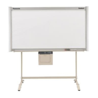
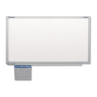
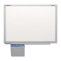
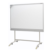
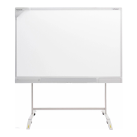
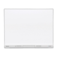
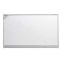
Detailed technical specifications for different models of the unit.
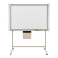
Step-by-step guide for setting up and installing the unit.
Procedures for verifying unit functionality and initial setup after installation.
Detailed steps for securely mounting the unit onto a wall.
List of error codes, their possible causes, and troubleshooting steps.
Common issues related to printing and their solutions.
Actions needed after replacing or servicing specific components or assemblies.
Procedures for disassembling and assembling the scanner components.
Detailed instructions for disassembling and assembling the control box unit.
Methods for accessing the unit's service mode for diagnostics and settings.
Explanation of the different modes available for service and initial setup.
Overview of operations and adjustments performable within the service mode.
Pinout and signal descriptions for the SD Memory Card connector.
Pinout and signal descriptions for the connection between CONTROL and MOTOR DRIVE boards.
Pinout and signal descriptions for the connection between CONTROL and SCANNER boards.
Pinout and signal descriptions for the connection between CONTROL and POWER boards.
Detailed circuit diagram for the main control board.
Circuit diagram for the panel board containing controls and display.
Circuit diagram for the motor drive board controlling mechanical movement.
List of components and their part numbers for the control board.
List of components and their part numbers for the scanner board.
| Multi-Touch | Yes |
|---|---|
| Frame material | Aluminum |
| Power Supply | AC 100-240 V, 50/60 Hz |
| Touch Technology | Infrared |
| Connectivity | USB |
| Operating System Compatibility | Windows, macOS |