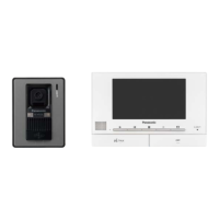
Installing the door station
Important:
LOn the bottom surface of the door station, there are holes to allow water to drain.
Do not cover them up when installing.
1 Remove the mounting base.
A Open the screw
cover.
TScrewdriver
Mounting base
B Loosen the
mounting screw.
Water drain
holes
2 Attach the mounting base to the wall securely using the wood screws (3.8 mm x 20 mm).
LInstall the mounting base on a vertical fl at wall.
LBefore drilling, refer to “Before installation” for installation location.
83.5 mm
Wall
Wire (Not included)
Mounting base
Wood screws
3 Adjust the camera angle using the camera angle control lever.
LThe angle can also be adjusted to the left
or upper left.
<Examples of camera angle>
<Facing forwards> <Facing upwards> <Facing right> <Facing upper right>
Rear view
Camera angle
control lever
Left
(maximum 15°)
Right
(maximum 15°)
Upwards
(maximum 15°)
Important:
LWhen the camera angle is adjusted to the upper left or upper right, the image may be slightly
distorted.
4 Connect the wire, then mount the door station to the mounting base.
C Fasten the screw, then
close the screw cover.
A Unscrew the screws.
Push in the wire to the terminal connectors
(non polar), then tightly fasten the screws.
Wire (connecting to the main monitor station)
B Mount the door station to
the mounting base.
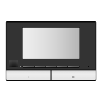
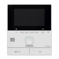
Installing the main monitor station
1 Attach the mounting bracket to the wall securely using the wood screws (4 mm x 16 mm).
LInstall the mounting bracket on a vertical fl at wall.
LBefore drilling, refer to “Before installation” for installation location.
83.5 mm
Wood screws
Wall
Wire (Not included)
Mounting bracket
2 Attach the wires connected to the door station to the terminal connector.
LConnect the wire correctly according to “Wiring schematic diagram”.
LWhile pressing on the button with a pointed object such as a screwdriver, insert the wire into
the terminal connector. (To disconnect a wire, press on the button while pulling out.)
Wire from the door station
Stripped end of
the wire
9 mm
Terminal
connector
Button
3 Mount the main monitor station to the mounting bracket.
A Fit into position as shown in the fi gure.
B Push the main monitor station down until it is secure.
B
A
4 Connect the plug into an AC outlet (100 – 240 V AC).
To connect the plug to the power outlet which is not easily accessible
Important:
LIf you want to connect the plug to the power outlet which is in the wall or is not easily
accessible, install a main disconnect device near the main monitor station.
LUse a main disconnect device with minimum 3 mm contact spacing inside the device and
showing “ON” and ”OFF”.
To use an existing wire in your home
1 Be sure to turn off the power and confi rm that the wire type is CAT-3 (ø0.5) or 22 AWG
(ø0.65). If the wire type is not CAT-3 (ø0.5) or 22 AWG (ø0.65), change the wire to either of the
specifi ed wire types.
2 Install the main monitor station and the door station.
3 Turn on the power.
 Loading...