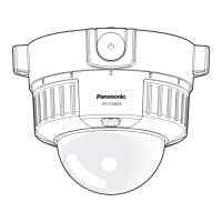
54
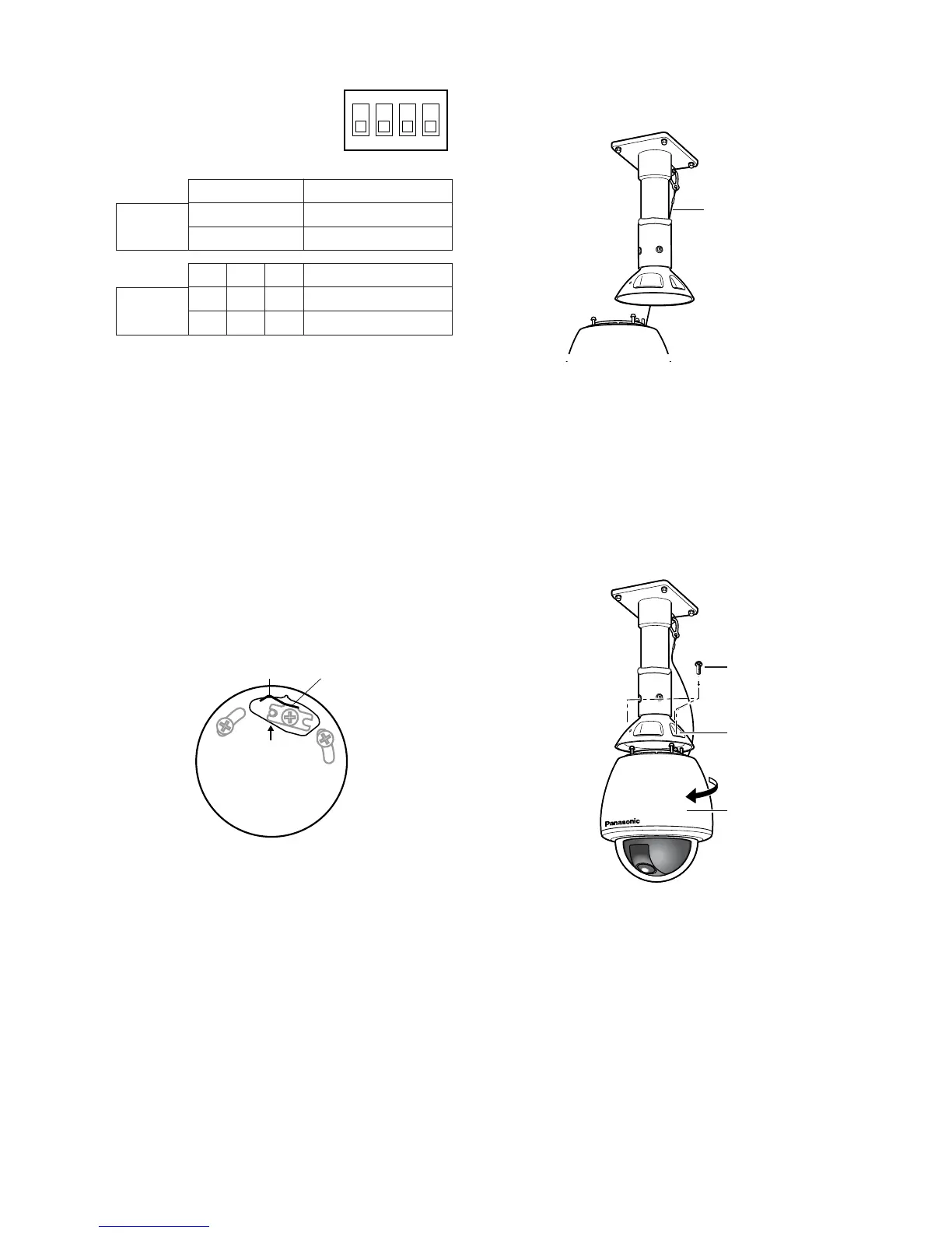
(2) Be sure to hook the fall prevention wire
into the bracket.
(3) Fix the camera to the upper base.
• Move the camera up so that its
guide pins fit into the guide holes of
the upper base.
• Turn the camera counter-clockwise
to the end, viewed from the bottom.
• Fasten 3 screws.
Full duplex (4 line)
*
BP 2
BP 1 Function
Switch
position
Function
Switch
position
RS485 Setting
The 4-bit DIP switch is used for
RS485 termination.
ON
OFF
Termination ON
Termination OFF *
BP 3 BP 4
ON ON ON
OFF OFF OFF
Half duplex (2 line)
Notes:
• Defaults are marked with
*
.
• BP stands for Bit Position.
• Full duplex is not available in a daisy chain
connection. (Panasonic system controllers
only)
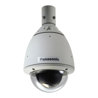
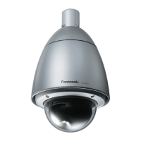
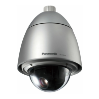
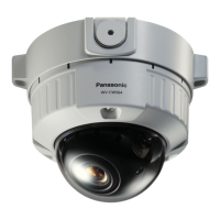
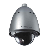
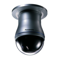
5. Mounting the camera
(1) Aim the “START” arrow at the bent por-
tion of the leaf spring.
 Loading...