16
0
1
2
345
6
1/2 1/2 1/2 1/2 1/2 1/2
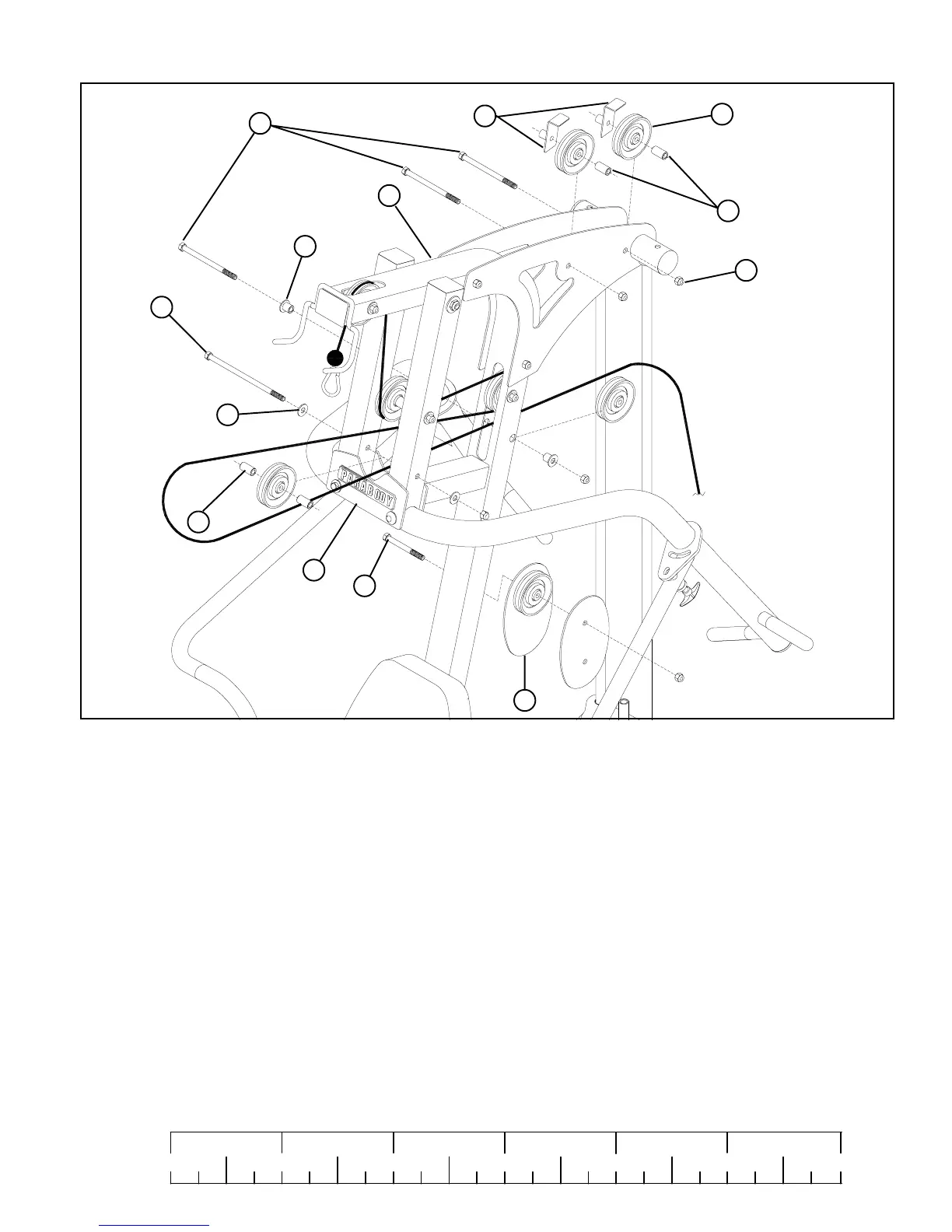
FIGURE 14
• Refer to cable ILLUSTRATION “A” on page 14 for cable routing while installing pulleys.
STEP 14:
• Assemble one 3-1/2” PULLEY (24) to the FRAME (1) using one 3/8 X 3-3/4” BOLT (30), two 3/8 X 1-1/16”
FLANGE SPACERS (42), one 3/8” LOCK NUT (34) and tighten securely
• Assemble one 3-1/2” PULLEY (24) into the PRIMARY PIVOT (9) lower hole using one 3/8 X 8-3/4” BOLT (31),
two 3/8” FLAT WASHERS (36), two 3/8 X 1-1/2” SPACERS (44) and one 3/8” LOCK NUT (34) and tighten securely.
• Assemble two 3-1/2” PULLEYS (24) between the left and right BOOM PLATES (4) and (5) using two 3/8 X 3-3/4” BOLTS (30),
two 3/8 X 1” SPACERS (43), two 3-1/2” CABLE GUARDS (38) and two 3/8” LOCK NUTS (34)
• Loosely assemble one 3-1/2” PULLEY (24) between PULLEY PLATES (12) using one 3/8 X 1-3/4” BOLT (27) and
one 3/8” LOCK NUT (34).
30
31
43
42
44
36
27
12
9
1
34
24
3/8 X 1-3/4”
3/8 X 3-3/4”
38
3/8 X 8-3/4”
 Loading...


