18
• Refer to cable ILLUSTRATION “A” on page 14 for cable routing while installing pulleys.
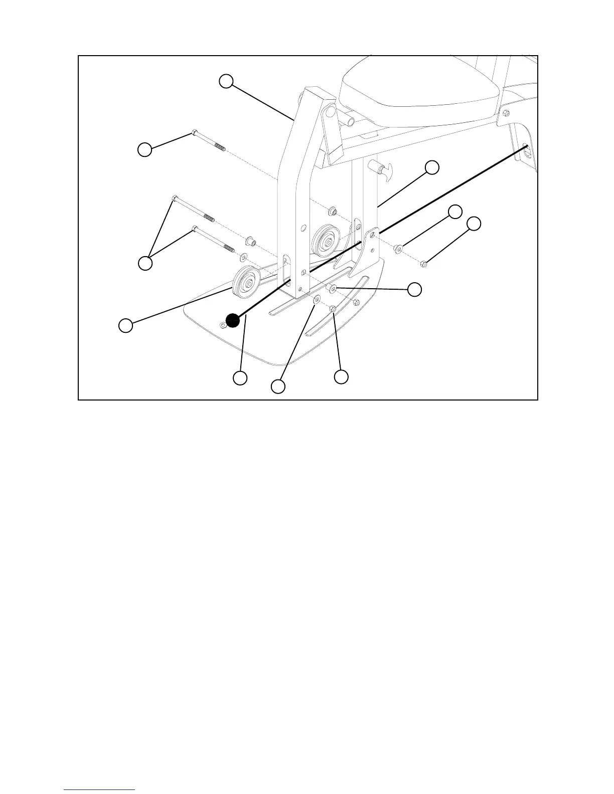
STEP 16:
• [CABLE MUST BE POSITIONED BETWEEN PULLEY AND LOWER BOLT ASSEMBLY ON
LEG PEDESTAL (11) AND FRAME (1)]
30
34
34
24
36
11
1
FIGURE 16
3/8 x 3-3/4”
3/8 x 3”
29
42
• Securely assemble the ball end of the LOW CABLE (21) and one 3-1/2” PULLEY (24) to the LEG PEDESTAL (11) using two
3/8 X 3-3/4” BOLTS (30), two 3/8” X 1-1/16” FLANGE SPACERS (42), two 3/8” WASHERS (36), and two 3/8” LOCKNUTS (34).
(NOTE: The LEG CABLE (21) should be routed over the retaining bolt as shown in FIGURE 16.)
• Securely assemble one 3-1/2” PULLEY (24) and two 3/8 X 3/4 FLANGE SPACERS (41) to the FRAME (1) using one 3/8 X 3”
BOLTS (29), and one 3/8” LOCKNUT (34). (NOTE: The LEG CABLE (21) should be routed over the retaining bolt as shown
in FIGURE 16.)
21
41
 Loading...


