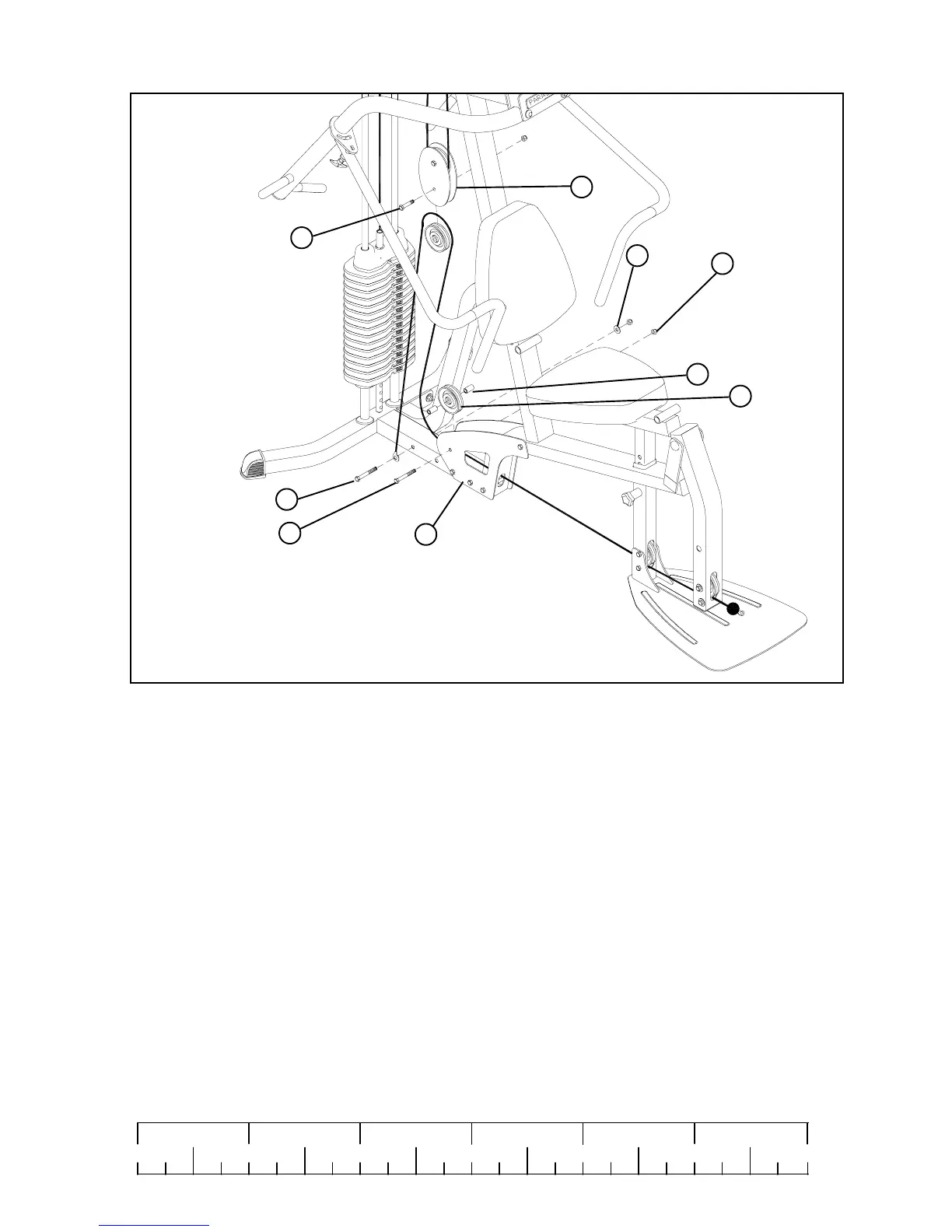
• Refer to cable ILLUSTRATION “A” on page 14 for cable routing while installing pulleys.
STEP 17:
• Secure end of LOW CABLE (21) using one 3/8 x 3-3/4” BOLT (30), one 3/8” FLAT WASHER (36) and one 3/8” LOCK NUT (34)
as shown in FIGURE 17
• Loosely assemble one 3-1/2” PULLEY (24) between the PULLEY PLATES (12) using one 3/8 X 1-3/4” BOLT (27), and one
3/8” LOCK NUT (34).
• Assemble one 3-1/2” PULLEY (24) between BASE PLATES (3) using one 3/8 X 3-3/4” BOLT (30), two 3/8 X 1” SPACERS
(43), one 3/8” LOCK NUT (34) and tighten securely.
• Tighten both 3-1/2” PULLEYS (24) located on PULLEY PLATES (12)
34
24
30
27
43
3
12
FIGURE 17
3/8 X 3-3/4”
3/8 X 1 -3/4”
36
19
0
1
2
345
6
1/2 1/2 1/2 1/2 1/2 1/2
3/8 X 3-3/4”
30
 Loading...


