8
0
1
2
345
6
1/2 1/2 1/2 1/2 1/2 1/2
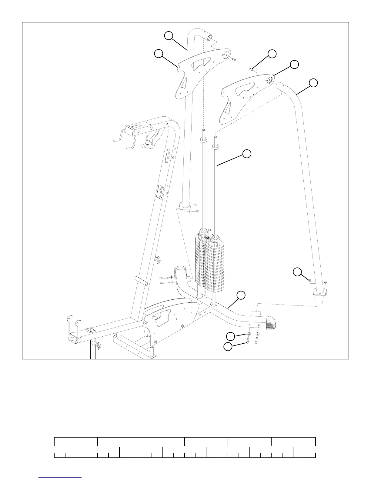
STEP 5:
• Carefully slide the RIGHT (N) and LEFT (M) REAR UPRIGHTS over the GUIDE RODS (AC ) as shown in FIGURE 5 and SECURELY
assembly the RIGHT (N) and LEFT (M) REAR UPRIGHTS to the BASE (B) using four 3/8 X 3-3/4” BOLTS (6), four 3/8” WASHERS (18)
and two 3/8” LOCK NUTS (19) as shown in FIGURE 5.
• SECURELY assemble the RIGHT (E) and LEFT (D) BOOM PLATES to the RIGHT (N) and LEFT (M) REAR UPRIGHTS using two 3/8 X
3/4” BOLTS W/LOCKTITE (14) as shown in FIGURE 5.
3/8 X 3-3/4” 6
14 3/8 X 3/4”
18
19
AC
M
D
E
N
B
 Loading...


