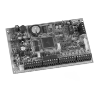
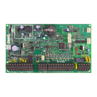
DGP-848 Control Panel 3
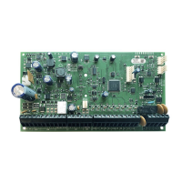
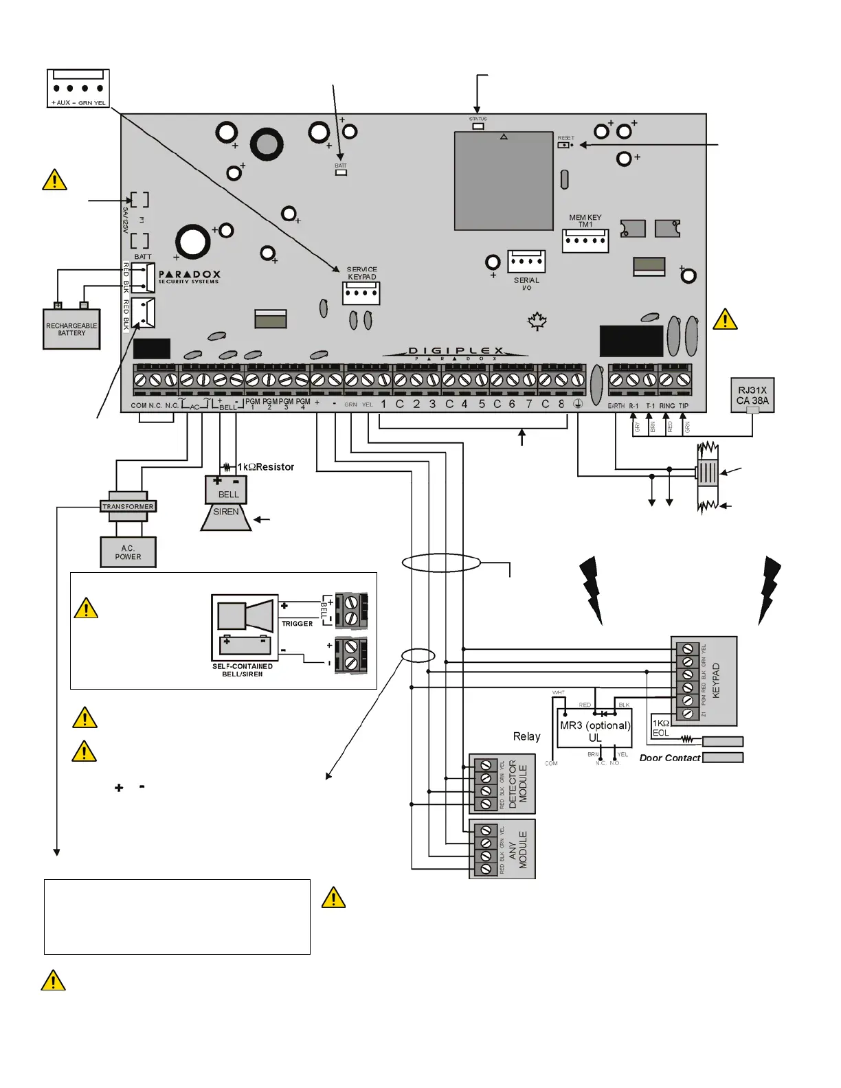
Figure 3: Digiplex Control Panel PCB Layout
For UL/C-UL warnings and requirements, see Warnings on page 60.
For the hardwire
connections, see Single
Zone Connections on
page 6. and Double
Zone Connections on
page 7..
When installing the combus wires in a noisy
environment, or when connecting the combus across
separate buildings, you must use a shielded cable.
Refer to Connecting the Combus in Noisy
Environments on page 6.
The combus supports a maximum of 95 modules.
Although external power supplies can be used to
provide power to modules connected far from the
control panel, the final module on the combus should
not be more than 3000 feet (914m) away.
Before adding any module to the control panel,
make sure you shut down the panel by removing
AC power and the battery.
Four pin connector can be
used for quick installation of a
Digiplex keypad or module.
Charging and battery test LED
(every 64 seconds)
“STATUS” LED: Short flash = Panel OK
Long flash = TLM Fault
Constant = Dialer on-line
OFF = Panel error/off-line
Reset
jumper
Warning:
Disconnect
telephone line
before servicing
Ground
clamp
Cold
water pipe
grounding
AWG#14 single
conductor solid
copper wire
To metallic
enclosure
To provide maximum lightning
protection, we strongly
recommend having separate
earth connections for the dialer
and zone ground terminals.
COMBUS
AUX POWER
Refer to transformer requirements below for Auxiliary Power Output.
Also, refer to Calculating Power Requirements on page 4. To
connect additional wiring to auxiliary power, use the red (+) and
black (-) keypad connectors. Auxiliary power will shut down if current
exceeds 1.1A.
Transformer Requirements: minimum: 16VAC 20VA
Auxiliary Supply can provide: typical: 600mA
max.: 700mA
Usable Battery Charge Currents: 350mA
Warning: Improper connection may
result in damage to the system.
Warning: During power up, the panel
will perform a module scan that lasts
between 30 and 120 seconds.
BELL OUTPUT
will shut down if
current exceeds 3A.
PGM1: 100mA
PGM2: 50mA
PGM3: 50mA (opt)
PGM4: 50mA (opt)
PGM5
(optional
5A relay)
Optional connector
can be used to
recharge another
battery in the
system.
Warning:
Disconnect the
battery before
replacing the
fuse.
A 40VA transformer is required when
selecting the 850 mA battery charge
current. Using a 20VA transformer with
a battery charge current of 850mA may
damage the system.
Connection for Self-contained Bell/Siren
The sum of the
current drawn from
the BELL and AUX
must be limited to 2.0A.
Exceeding this limit will
overload the panel power
supply and lead to complete
system shutdown.
 Loading...