Installation
The PCS265V8 can be installed on a variety of surfaces, using appropriate mounting hardware. Install the module as close to the panel as
possible. Refer to Figure 2 for more information.
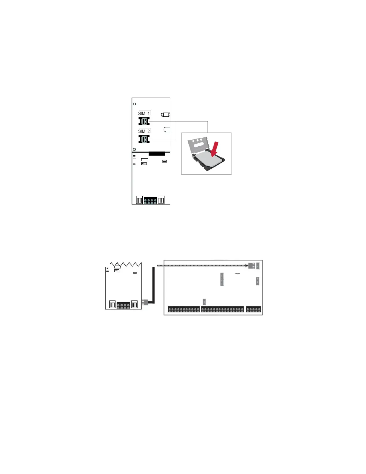
SIM Card Connection
The PCS265V8 supports two nano LTE provider SIM cards. To install the SIM cards, open the SIM Card tray and insert the card into base, as
shown. SIM 1 is used as “Primary” and SIM 2 for “Backup”. If only one SIM card is used, insert into SIM 1.
Note: SIM Card 2 can only be configured via SMS.
Figure 3
Panel Connections
Connect the PCS265V8’s serial out to the serial connector on the panel.
•
For LTE reporting, connect to the Serial port of the panel.
Figure 4
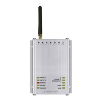
External Antenna Connection
Use the ANTK4G LTE external antenna kit for PTCRB installations or to improve RF reception if your module’s signal strength is weak. External
antenna kits and extension kits are purchased separately.
Powering-up the PCS265V8
Once your hardware connections are completed, the PCS265V8 module will begin its power up sequence.
•
Power LED will turn solid green.
•
Status LED will turn solid green.
•
SIM card 1 LED will slowly flash red while searching for the GSM network; once found the LED will be solid purple.
When configured for LTE reporting, you will need to configure network provider information. Refer to the Programming section.
Note: The battery is optional. If a battery is used/installed, do not allow the battery to deplete and ensure that the battery is replaced when low.
The battery function is to support power shut down and not to be used as backup as defined in EN50131-6.