Page 5
RTX3 Board and Connectors
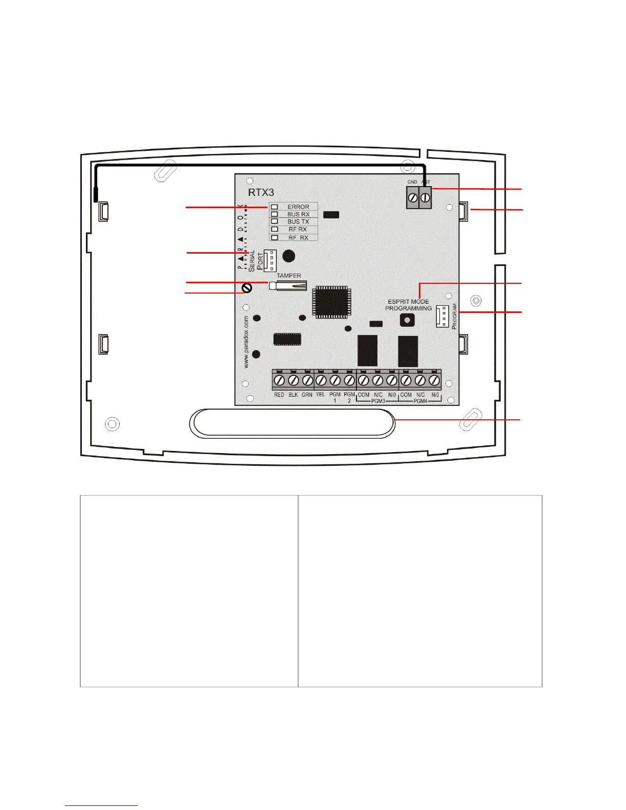
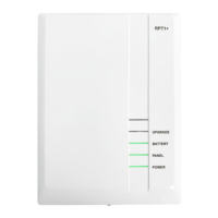
The following graphic displays the RTX3 board and connectors.
Figure 1: RTX3 Board and Connectors
1. LED display (see LED
Feedback
on page 8)
2. Firmware upgrade serial
connector (see
Firmware
Upgrade
on page 20)
3. Anti-tamper switch
4. PCB screw
5. Antenna
6. Mounting clips
7. Mode Programming button: Used
for programming Stand Alone
RTX3 modules (see
Stand Alone
Programming
on page 17 and
System Reset (see System Reset on
page 7)
8. Program connector: Connect the
keypad to the Program connector
to program in Stand Alone mode
9. Wiring slot