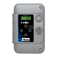
023-064X Technical Manual
70-PHW-1018-R3.2 MTA 8.5 023-064X Refrigerant Leak Detector Manual.docx 7
Open a knock-out hole for wiring.
Wire the power on 24VAC+ and the common on 24VAC-
Wire the Sensor A signal output from AN1 and the signal ground on the G terminal
Make sure the jumper above the AN1 terminal is towards down to send 2-10V signal on the AN1 output
Place the AN2 jumper towards down to send 2-10V signal on the AN2 output
Place the according jumper towards up in the case you need to send 4-20mA signal on the output.
Dry contact wiring on the terminal block NO C NC to be connected to the manual pull station.
The jumper EOL is not used in this application and don’t have any effect.
Replace the cover and screws.
3 Local user settings
3.1 Sensor configuration
Press the right arrow button to enter configuration
Use 0 AL1 to determine the threshold of Sensor A at which the relay should operate (default is
400ppm). Setting 1 A1Del is the set time (default is 30 sec), 2 A1Off is the reset time (default is 20 sec).
The relay reset by its own, there is no need to acknowledge an alarm.
To set the audible alarm use the 6 AL3, 7 A3Del and 8 A3Off
See section 3.2 User settings list.
Default display scale is R22 or R507 and it can be changed by the user.
To view the current settings on the model 023-064X, press right until you reach the desired setting.
To modify press up or down. See section User settings list for more information.
To save, press left and up buttons at the same time. The appearance of **OK** will confirm successful save.
Example: To set the reading scale for R141b you have to change the gas type as follow:
Press right to display the value for 57 Ref-A (hold arrow to speed up) then press up to change gas type (see
available gas type and their ppm range at section Ordering information).

 Loading...