1-3 English
650, 650V & 650G QUICKSTART
Before You Start
This document covers the steps necessary for a basic start-up of the 650, 650V & 650G (referred to as 650X)
drives. Drive start ups should be performed by qualified electrical technicians who are familiar with AC drives
and their applications. For detailed installation and safety information refer to the relevant Product Manuals.
Ensure that all local electric codes are met while installing the drive. Check that all live parts are covered to
protect against electric shock and that unexpected rotation of the motor will not result in bodily harm or injury.
This document expects that the drive is already installed in its intended location and that all relevant installation
procedures have been followed. Please ensure that the drive has adequate ventilation so that ambient
temperature does not exceed 40°C (104°F) under normal operating conditions.
To access the terminals, slide down the terminal cover, while applying slight pressure on the drive label.
Frame Ratings
Frame 1 0.3 – 1 HP 230VAC 1 ph
0.25 – 0.75kW
Frame 2 1.5 – 2 HP 230VAC 1 ph
1.1 – 1.5kW
0.5 – 3 HP 460VAC 3 ph
0.37 – 2.2kW 400VAC
Frame 3 3 – 5 HP 230VAC 3 ph
2.2 – 4kW 400VAC
5 – 10 HP 460VAC 3 ph
3 - 7.5kW 400VAC
Control Modes
Volts/Hertz mode – Basic open loop operation, used in fans/pumps and multi-motor applications.
Sensorless Vector mode (650V & 650G only) – Tight speed regulation with good transient torque capability,
without the need for speed feedback.
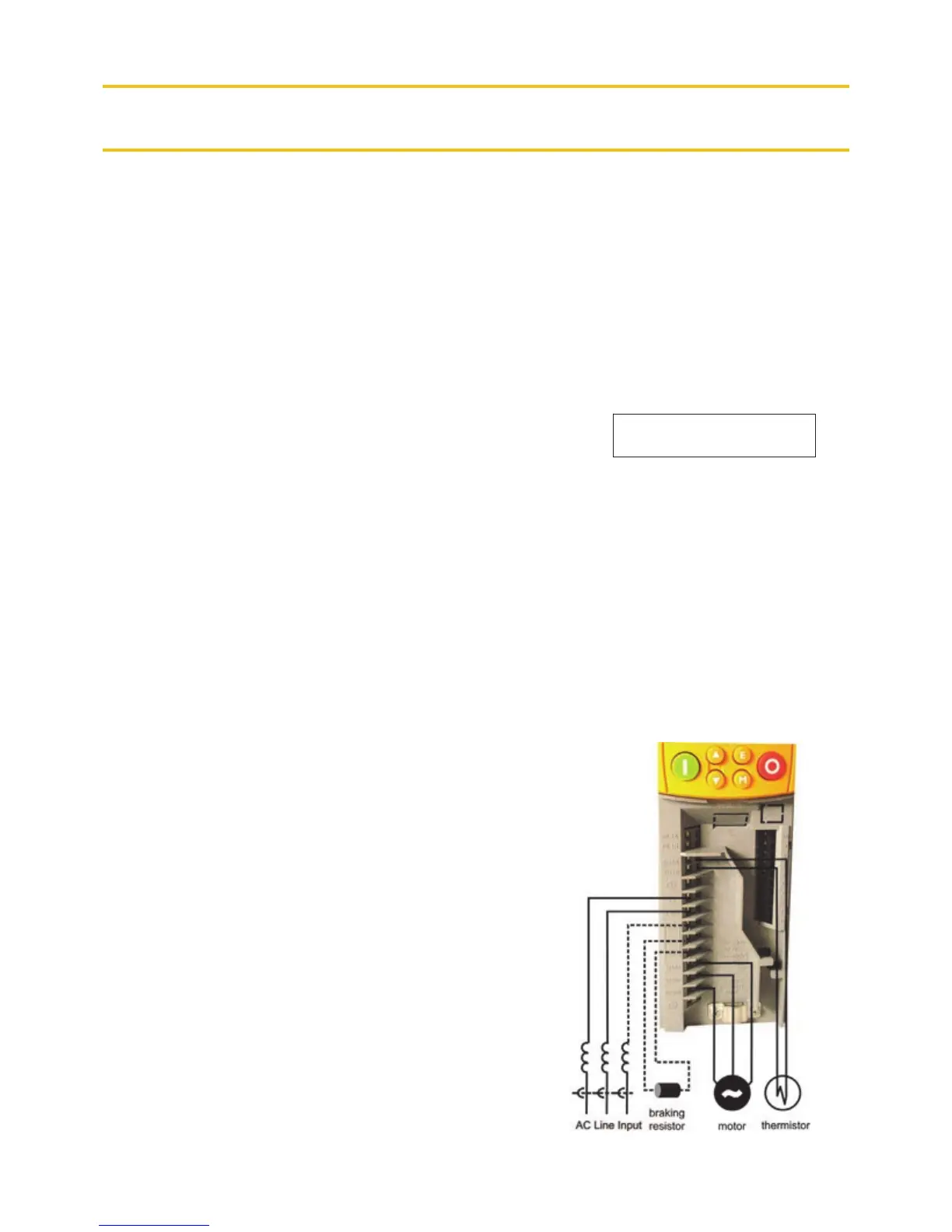
Power Connections
The power terminals shown are for frame 2.
Although other frames may vary slightly in appearance, their
terminal designations and functionality are very similar.
Single-phase supply to L1, L2/N.
3-phase supply to L1, L2, L3.
Motor connections to M1, M2, M3.
Brake resistor between DC+, DBR
NOTE: Frame 1 & 2 230V units are not fitted with a
braking module. Do not use a braking resistor on them.
Motor thermistor to Th1A, Th1B.
Ground lugs are provided for each power circuit. Follow proper
grounding and shielding methods as described in the Product
Manual.
If stop time is expected to be less than the natural coasting time
of the load, connect the braking resistor across DC+ and DBR
(see brake resistor note above).
For larger sizes, see 650V
Quickstart HA470679U200