8
Parker Autoclave Engineers
Instrumentation Products Division
Erie, PA USA
www.autoclave.com | Cat. 02-9221ME
Make sure blades are clean and free of burrs that
could scratch the machine parts. Push chasers into
the matching numbered slots until there is a slight
click indicating the chaser is seated properly. Chaser
spring plungers prevent chasers from falling out.
5.3.5 Move die head into closed (cutting) position.
Firmly pull
trip yoke arms forward, away from the motor, being sure
to continue the forward motion after the head release lever
snaps into locking position and until head locks into the
closed (cutting) position.
Set-up Die Head
5.4 Adjust Pitch Diameter
5.4.1 Pitch Diameter - With the die head in the closed position,
check the pitch diameter of cutting dies by attempting to
screw a standard factory threaded nipple into the die head.
5.4.2 If the piece does not go in smoothly, loosen adjusting ring
binding screw using a 5/32" allen wrench (Figure #5).
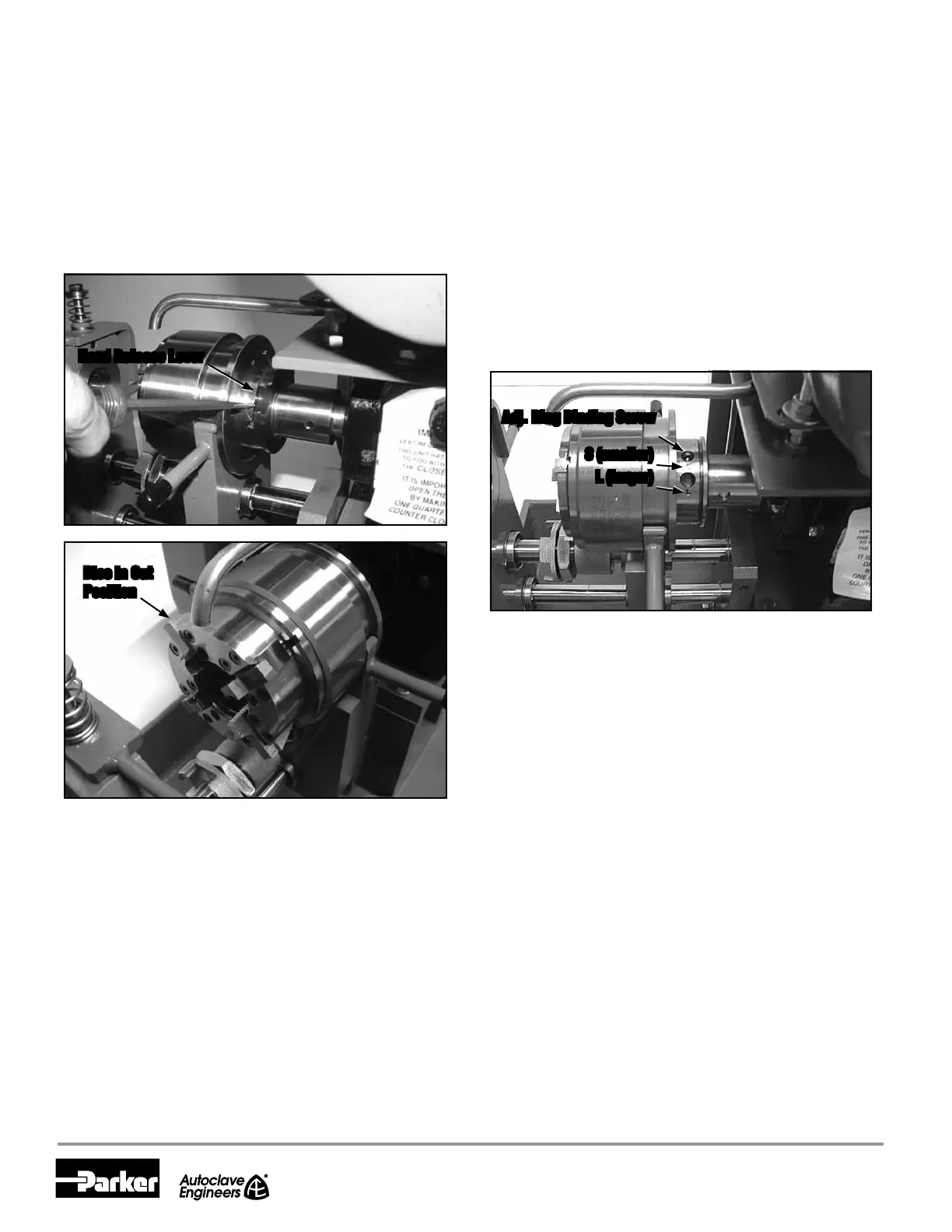
Head Release Lever
Dies in Out
Position
Figure 8
Moving die head to extreme position for chaser insertion by
pressing head release lever
Note: You may have to start and stop the machine quickly to
get the die head to stop spinning in a good
position to have access to the binding screw.
5.4.3 Then insert a metal pin tool or rod into the hole in the adjust-
ing ring next to the adjusting ring binding screw and use
the tool to rotate the adjusting ring until the desired pitch
diameter is obtained. The die head adjusting ring is marked
with an “S” (smaller pitch diameter) and an “L” (larger pitch
diameter) to indicate the direction to turn the ring to adjust
the pitch diameter smaller or larger (Figure 9).
5.4.4 Tighten adjusting ring binding screw before cutting a thread.
5.4.5 Cycle the die head through the closed and open positions to
ensure the new thread depth adjustments take effect.
5.5 Set Thread Length
Adjusting the spacer head assembly located under the
die head sets the proper distance for thread length. Stop
collar adjustment gives ne adjustment of thread length.
5.5.1 Rotate tube-stop 90° to the left by lifting up, rotating
and letting down (Figure 10). Insert coned, unthreaded
tubing loosely through both collets. Bottom tube end
against tube-stop and tighten collet nut on the inner yoke
by hand. Then rotate tube-stop back to original position
and tighten collet nut on the inner yoke with a spanner
wrench. Pull the inner yoke away from the motor and
against the frame bracket. Tighten the collet nut on the
outer yoke with a spanner wrench.
5.5.2 Close the die head by pulling the two handles on the die
head trip yoke away from the motor.
5.5.3 Carefully slide the collet assembly (this consists of the
inner and outer yokes) with mounted tubing forward until
the cone of the tube touches the chasers.
Adj. Ring Binding Screw
S (smaller)
L (larger)
Figure 9
Illustration of adjusting ring
 Loading...