5
Instruction Manual
Compact EHA
Bulletin HY22-3200B
Parker Hannifin
Oildyne Division
Commissioning and Safety
Installation
Locating EHA
The unit should preferably be installed indoors in a clean, dry
environment with an ambient temperature of 16° to 37°C (60°F
to 100°F).
Parker Oildyne products should not be installed where they are
at risk of objects falling from overhead or where there is any risk
of impact with external objects.
Mounting the Unit
Each Parker Compact EHA is designed to be mounted and
connected in a specifc way. Be sure to use the proper size
mounting hardware to match the mate end on the rod or base
end of the EHA.
Connect one end of the EHA unit to its corresponding mount on
the machine.
The load must be supported by its own guidance system.
The axis of the cylinder and that of the load should not be
unduly displaced to ensure that there are no imposed side
loads following installation or signicant reaction forces of the
cylinder. It is the user’s responsibility to properly position the
unit to keep the load in axial alignment with the center line of the
EHA rod. The degree of accuracy needed will vary from unit to
unit based on the conguration so every effort should be made
to be as accurate as possible.
The unit should be positioned in the machine to ensure good
ventilation.
For environmental protection a rubber gaiter or boot may be
placed round the piston shaft. This serves to prevent access to
the moving piston shaft but this is only an option. The provision
of a rubber gaiter or boot for safety purposes is not mandatory.
However it is recommended that a gaiter or boot might be tted
if the end user does not intend to provide any alternative form
of protection such as guarding. The piston shaft is stainless
steel and is resistent against wear. But, if a dusty environment is
involved a gaiter or boot may still be used to protect seals.
If the unit has a yellow sticker designating “THIS SIDE UP” or
“THIS END UP”, make sure that the unit is mounted with that
sticker up, or on top of the unit.
If the unit is mounted to the machine using bolts (user supplied),
make sure to use the correct tightening torque to ensure a
secure mounting and no damage to the hardware.
Electrical Service Connections
Connect the motor to the power source following good
practices as outlined in the National Electric Codes and any
local codes which may apply. Verify that the available Voltage
is the same as the Voltage identied on the label. A
suggested
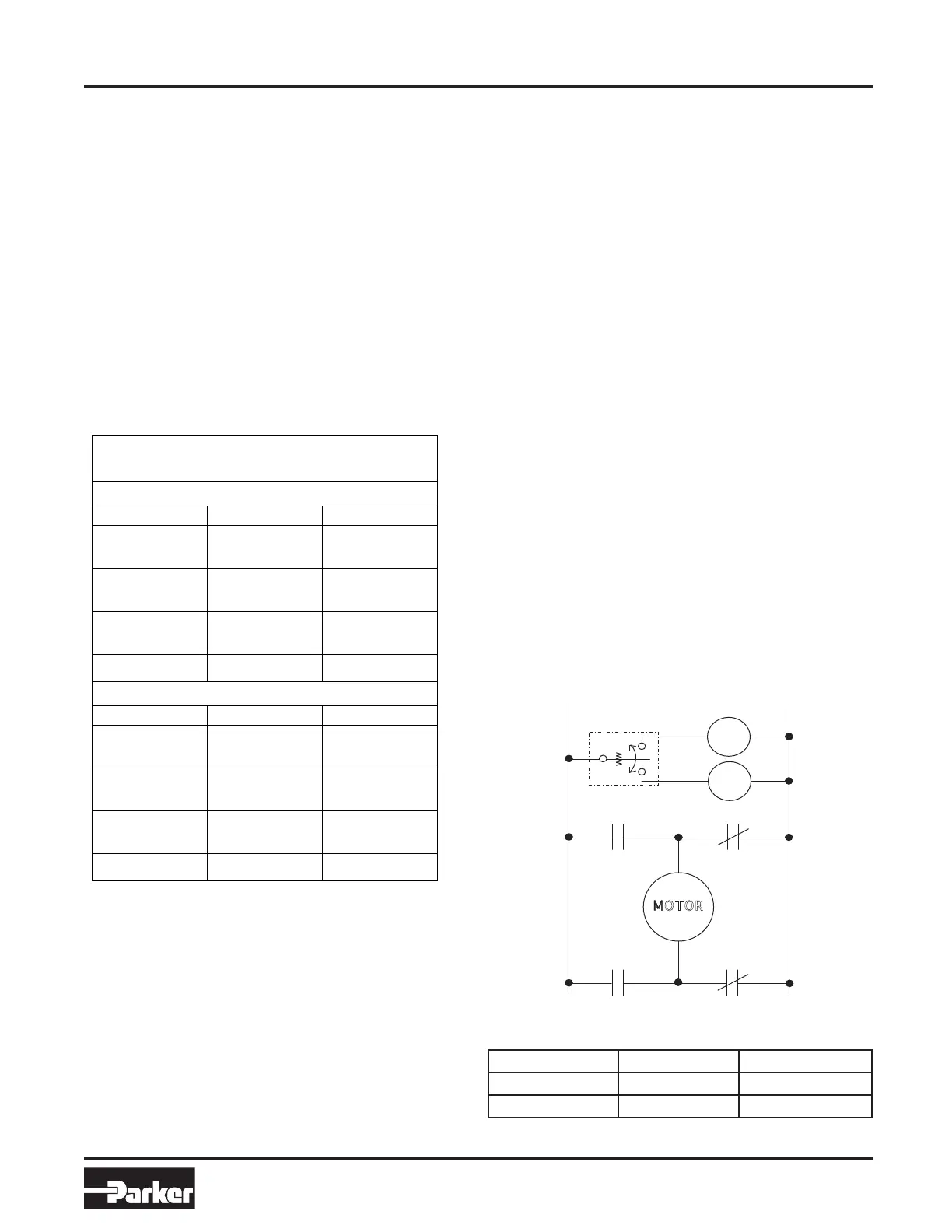
example for wiring is illustrated in Figure 6.
The blue lead (positive) extends the unit and green lead
(positive) retracts the unit. Refer to Figure 7 for wire colors and
corresponding operation.
Once the motor is connected, extend or retract the unit to align
the pin connection or specied mounting at the free end of the
EHA with the machine mounting. Attach to the machine using
appropriate mounting hardware.
The machine in which the EHA is incorporated should be
bonded to earth. Each EHA unit must be bolted to the frame of
the machinery in which it is incorporated. Therefore, if lightening
strikes, this will immediately be returned to ground potential.
Figure 6
Function Positive Ground
Extend Blue Green
Retract Green Blue
Figure 7
Pin to Pin Dimensions for Units with Spherical
Tolerances
Tolerances
Pin to Pin Dimensions for
Units with Spherical Bearings
Sperical bearings on either base or end should have jam nuts
torqued 350.3Ncm (31 ft-lbs).
SPDT Center Off Toggle
Switch
 Loading...