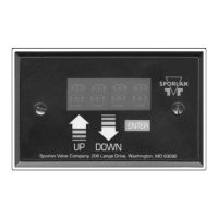
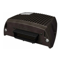
Do you have a question about the Parker Sporlan Subcool Control and is the answer not in the manual?
Lists necessary tools for installing the controller and its components.
Details the process of entering and configuring basic system variables for the controller.
Outlines the specifications and wiring for Modbus communication.
Explains how Celsius and Bar values are scaled for Modbus data transfer.
Details how to configure controllers for network communication via RS-485.
Discusses common sensor issues, alarms, and how to test them.
Details how to test pressure transducers and their connections for accuracy.
Defines the selectable valve types for the EEV based on steps.
Lists and explains the selection of refrigerants supported by the controller.
Specifies the types of pressure sensors (Absolute/Gauge) that can be connected.
Details the selectable pressure ranges for the connected pressure transducer.
Key setpoints for liquid outlet temperature, return gas limit, subcooler differential, and superheat.
Specifies the refrigerant to calculate saturation temperature based on suction pressure.
Major PID gains for liquid and superheat control affecting system response.
Configuration for Modbus network address, baud rate, and parity.
Settings for connected temperature and pressure sensor types and ranges.
Adjustments for pressure and temperature sensor readings for accuracy.
Definitions for liquid outlet, return gas, subcooler differential, and superheat setpoints.
Definition of selected refrigerant for saturation temperature calculation.
Definitions for major PID gain coefficients for liquid and superheat control.
Definitions for Modbus network address, baud rate, and parity.
Definitions for temperature and pressure sensor types and ranges.
Instructions for properly mounting the pressure transducer onto the system.
Guidance on correctly positioning and attaching temperature sensors for suction and liquid lines.
| Type | Subcool Control |
|---|---|
| Manufacturer | Parker Sporlan |
| Mounting | Panel Mount |
| Power Supply | 24 VAC |
| Function | Controls subcooling in refrigeration systems |


