Bulletin 100-50-5.2 – Page 3
1. Installation
Refer to Appendix I - Wiring Diagram and Appendix J -
Sensor Installation
TOOLS REQUIRED:
• Small flat screwdriver for terminal connections
• Cordless screwdriver
• Phillips and flat screwdrivers
• Needle-nose pliers
• Wire cutters
• Scotch-Brite
TM
pad
• Two #8 x ½” self-tapping screws to mount DIN rail
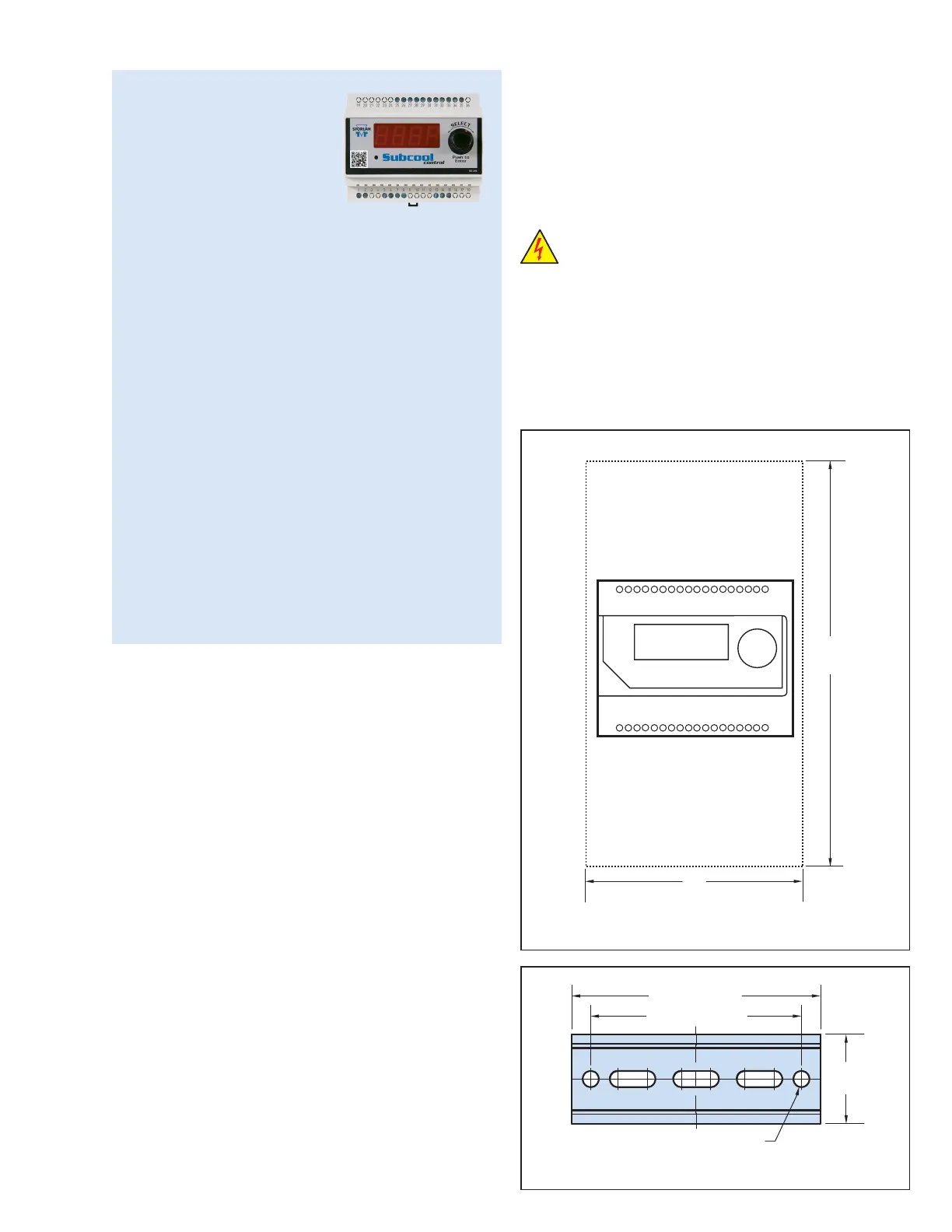
1. Mount the controller in a rain-tight, protected location
using the supplied DIN Rail. To leave enough working
space, the suggested mounting area is 10 inches high
and 5 inches wide. The minimum depth is 3 inches. See
Figures 1 and 2.
2. Connect the subcool liquid temperature sensor wires
to terminals 29 and 30. The sensor is not polarized.
Maximum torque on screw terminals is 3.5 in-lbs.
3. Connect the suction temperature sensor wires to termi-
nals 31 and 32. The sensor is not polarized.
4. Connect the pressure transducer wires to terminals 33,
34, and 35. Sporlan has used transducer cables with two
wire color combinations; see Table 1 on page 4. If the
cable is spliced in the field to extend its length, ensure
the new wire is properly connected.
5. Connect terminals 25 and 26 to a digital input. A short
Introduction
The Sporlan Subcool
Control is a simple means
of controlling the Electronic
Expansion Valve (EEV) on
most liquid subcooling
systems. The Subcool Control provides liquid
temperature and superheat (pressure-temperature)
control for most common refrigerants. It displays
actual leaving liquid temperature, superheat,
suction pressure, valve position, controller status,
and alarms. It also allows manual control of the
valve position.
Features
• One dial for setting superheat and liquid tem-
perature
• One EEV control (bipolar step motor)
• 4-digit LED display
• Optional controller networking (MODBUS)
• One pressure input (Sporlan transducer)
• One digital input (for external switch or relay)
• Three temperature inputs (Sporlan surface or air
sensors)
5"
127 mm
10"
254 mm
Figure 1 - Recommended Mounting Clearance
1.5"
38 mm
.25" / 6.35 mm
4.0" / 102 mm
3.25" / 83 mm
Figure 2 - DIN Rail Detail
or a closed contact from an external relay will close the
valve for pump down. See Section 4 - System Operation,
on page 4.
6. Connect the Sporlan EEV wires to terminals 5, 6, 7, and 8.
7. Connect power to terminals 1 and 2. Transformer
requirements are 24 volts AC at 40 VA, Class II.
8. Remove the protective clear film from the front of the
Subcool Control.
WARNING: Use caution when working around
high voltage components. Safety covers should be
used for personal safety on high voltage panels.
NOTE: The Sporlan Subcool Control should be installed
only by a qualified professional. All other system com-
ponents (valves and sensors) should be supplied by
Sporlan to ensure compatibility and proper operation. For
optimal performance, a counterflow heat exchanger is
recommended. There are no user-serviceable compo-
nents inside the Sporlan Subcool Control. Opening the
case will void the warranty.

 Loading...


