Bulletin 100-50-5.2 – Page 17
APPENDIX K - MODBUS Memory Map
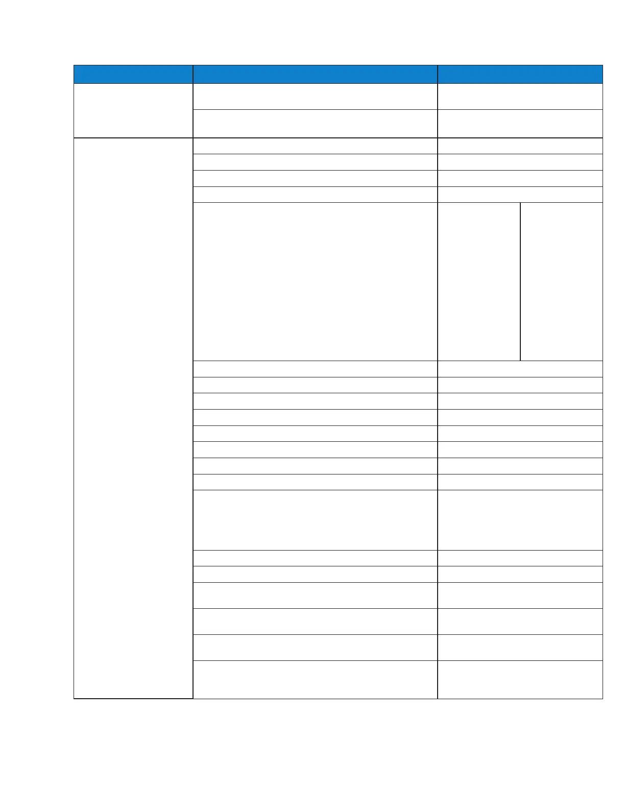
REGISTER ADDRESS/DESCRIPTION RANGE
Read Coils (0x01) 0. Manual Valve Enabled Flag 0 = Disabled
1 = Enabled
1. Manual Valve Duration Enabled Flag
0 = Disabled
1 = Enabled
Read Holding Register
(0x03)
0. Liquid Outlet Temperature Setpoint 10 to 100°F (-12.2 to 37.8°C)
1. Return Gas Temperature Limit 10 to 120°F (-12.2 to 48.9°C)
2. Subcooler Off Temperature Differential 0 to 30°F (0 to -16.7°C)
3. Superheat Setpoint 5 to 45°F (2.8 to 25°C)
4. Refrigerant Type 0 = R-22
1 = R-134A
2 = R-402A
3 = R-404A
4 = R-407A
5 = R-407C
6 = R-410A
7 = R-417A
8 = R-422A
9 = R-422D
10 = R-507A
11 = R-744
12 = R-245FA
13 = R-E5
14 = R-438A
15 = R-401B
16 = R-408A
17 = R-508A
18 = R-508B
19 = R-407F
20 = R-434A
21 = R-444B
22 = R-448A
23 = R-450A
24 = R-449A
25 = R-452A
26 = R-513A
5. Valve Maximum 0 to 100%
6. Liquid Proportional Coefficient 0 to 255
7. Liquid Integral Coefficient 0 to 255
8. Liquid Derivative Coefficient 0 to 255
9. Superheat Proportional Coefficient 0 to 255
10. Superheat Integral Coefficient 0 to 255
11. Superheat Derivative Coefficient 0 to 255
12. Cycle Time 1 to 10 seconds
13. Valve Type 0 = 1596
1 = 3193
2 = 2500
3 = 6386
4 = 400
14. Manual Valve Position 0 to 1000 (0 to 100.0%) Open
15. MODBUS Network Address 1 to 255
16. Pressure Units 0 = PSI
1 = BAR
17. Temperature Units 0 = FAHR
1 = CELS
18 Pressure Sensor Type
0 = ABSL
1 = GauG
19. Pressure Range
1 = 150 PSI
2 = 300 PSI
3 = 500 PSI

 Loading...


