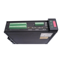
Do you have a question about the Parker Hauser COMPAX-S Series and is the answer not in the manual?
Defines the designation format for COMPAX device models, including performance class and variant.
Details information found on the device's rating plate, such as option name and serial number.
Explains COMPAX's use of the CANopen interface for enhanced flexibility and access to functions.
Describes the hardware components supporting the CANopen interface, including the CAN controller and transceiver.
Lists required components for a CAN-Bus system, including computers, cables, and COMPAX units.
Covers CAN-Bus settings like Node ID (Device Address) and Baud Rate, configurable via the front panel.
Illustrates the procedure for configuring bus parameters such as Node ID and Baud Rate using the device's front panel.
Details signed integer data types (Integer8, Integer16, Integer32) with their value ranges and lengths.
Details unsigned integer data types (Unsigned8, Unsigned16, Unsigned32) with their value ranges and lengths.
Provides an index of communication-specific objects, including general objects and settings for PDOs and SDOs.
Describes objects for device type identification and the error register for fault status.
Covers objects related to Number of PDOS, COB-ID SYNC, and Communication Cycle Period.
Details synchronization window length, device name, hardware, and software versions, plus node number.
Explains COB-ID for node guarding, guard period, and lifetime factor for bus monitoring.
Details COB-ID for emergency messages and the structure of emergency telegrams.
Covers SDO parameters, including the number of SDOs and configurations for SDO1 and SDO2.
Details communication parameters and mapping for receiving PDO1 and PDO2, including transmission modes.
Details communication parameters and mapping for transmission PDO1 and PDO2, including transmission modes.
Covers selection code for operating modes and the display of the actual operating mode.
Explains the control byte for program execution and the status byte for device messages.
Details the control word for activating device commands and setting virtual inputs, including bit assignments.
Describes how pop-up messages are generated and displayed via status words, activated by parameter P193.
Details various status indicators (S6, S9, S10, S11, S16_S17, S23_S26, S30) providing status information.
Explains the error object (STOERUNG) and provides a comprehensive list of COMPAX fault codes.
Details parameters for maximum permissible motor torque, rated torque, and actual torque values.
Covers motor nominal current, intermediate circuit voltage, and related status indicators.
Describes objects for setting target positions and reading actual drive positions, including handshakes.
Details position limits, positioning window, lag error window, and reference movement selection.
Explains status indicators (S3) and polarity settings for reversing orientation.
Covers traverse speed settings, reduction via override, and POSR 0 SPEED functionality.
Details speed step profiling options, including profiles with and without acceleration.
Describes maximum motor speed, maximum speed, traverse speed, and related status indicators (S4).
Details selection functions for acceleration ramp forms and time specifications for acceleration processes.
Explains time specifications for braking processes, quick stop commands, and reference movement acceleration.
Covers INPUT_WORD for digital input states and INPUT_MASK for input function assignment.
Details OUTPUT_WORD for digital output states and OUTPUT_MASK for output function release.
Describes setting and resetting outputs for comparator functions, both active high and active low.
Explains how to read and write program memory using command records in binary format.
Defines COMPAX command codes, their structure, operands, comparison operators, and arithmetical operators.
Details commands for program control, including Goto, Execute Program Record N, and Program Start.
Covers specific commands for COMPAX XX50 (WAITPOSA/R) and XX70 (Cam commands, memory operations).
Illustrates the state transitions of the COMPAX device when operating in Device Profile DSP 402 mode.
Lists and explains CANopen parameters for COMPAX devices, including P190-P196 and P203, P221-P224.
Provides a list of manufacturer-specific objects organized by their index number for easy reference.
Lists manufacturer-specific objects categorized by their associated command for functional grouping.
| Brand | Parker |
|---|---|
| Model | Hauser COMPAX-S Series |
| Category | Controller |
| Language | English |


 Loading...