EasyManua.ls Logo

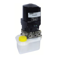
Parker Oildyne 108 Series - Unit Dimensions with G Reservoir; 165 Series Dimensions with G Reservoir; Dimensions with G Reservoir and Manifold

Parker Oildyne 108 Series
28 pages
To Next Page IconTo Next Page
To Previous Page IconTo Previous Page
Loading...
6
Instruction Manual
Oildyne 108/118 and 165/175 Series
Hydraulic Power Units
Bulletin HY22-3210A/US
Parker Hannifin
HPS Division
New Hope, MN 55428 USA
Note: All dimensions in mm (inches).
Ø
Ø
2X 5/16-18 UNC-2A
MOUNTING HOLES
3/8-16 UNC-2B X .44
(6.98)
177.4
(1.16)
29.4
(1.16)
29.4
(5.69)
144.5
(4.44)
112.8
(4.00)
101.6
(6.46)
164.1
(1.21)
30.7
(5.00)
127
(3.15)
80
(5.72)
145.3
(12.67)
321.8
(1.15)
29.2
(1.15)
29.2
(4.50)
114.3
Ø
Ø
(4.50)
114.3
(1.15)
29.2
(1.15)
29.2
(12.67)
321.8
(4.33)
110
(1.16)
29.4
(1.16)
29.4
(5.69)
144.5
(6.98)
177.4
(4.44)
112.8
(4.00)
101.6
(6.46)
164.1
(1.21)
30.7
(5.00)
127
(3.15)
80
PORTS
MOUNTING HOLES
3/8-16 UNC-2B X .44
2X 5/16-18 UNC-2A
With G reservoir and Solenoid Valve Manifold
165 Series
With G reservoir
Dimensions
Dimensions
THIRD ANGLE
PROJECTION

Table of Contents

Related product manuals