Do you have a question about the Parker Oildyne 108 Series and is the answer not in the manual?
Guides users on how to interpret the information provided on the product labels.
Details the meaning of each numbered element found on the product labels.
Explains the meaning and significance of various warning labels used in the manual and on products.
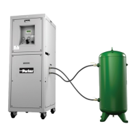
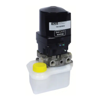
Provides a general description of the Oildyne 108/118 and 165/175 Series Hydraulic Power Units.
Provides dimensional drawings and measurements for the unit with specific configurations.
Details the overall dimensions of the 108/165 Series units when equipped with a 'C' type reservoir.
Lists the dimensional specifications for various motor types used in the power units.
Shows the physical dimensions of different reservoir types (A, B, C, F, G).
Presents detailed dimensional drawings for the 165 Series with a 'G' type reservoir.
Shows the dimensions of the unit equipped with a 'G' reservoir and solenoid valve manifold.
Illustrates the dimensions for 108/165 Series units using H, I, and J type reservoirs.
Displays the dimensions for 108/165 Series units using P, Q, R, and S type reservoirs.
Provides schematic diagrams for single direction hydraulic circuits (NN, WW).
Illustrates the schematic for the NN Single Direction circuit.
Shows the schematic for the WW Single Direction circuit with check valve.
Depicts schematics for S1-S4 circuits using Normally Closed (NC) solenoid valves.
Presents schematics for S5-S8 circuits using Normally Open (NO) solenoid valves.
Provides schematic diagrams for various reversible hydraulic circuits.
Shows the schematic for the RR Reversible circuit.
Illustrates the schematic for the LL Reversible Locking circuit.
Depicts the schematic for the RB Reversible circuit with back pressure.
Presents the schematic for the LB Reversible Locking circuit with back pressure.
Covers unpacking, checking for damage, and general preparation steps before installation.
Details the procedures for unpacking and inspecting the unit for transit damage.
Provides instructions on how to store the power unit if not installed immediately.
Outlines the steps and considerations for installing the hydraulic power unit.
Specifies ideal environmental and location criteria for installing the power unit.
Explains how to securely mount the power unit using the provided mounting holes.
Details how to connect the motor to the power source, including voltage and wiring.
Provides diagrams for connecting various motor types (AE, BE/IA, AM/BI, HA/HD).
Shows the wiring diagram for HD motors operating on 230 VAC.
Provides reversing schematics for PM motors (AE & BE).
Specific wiring diagram for AE and BE PM motors.
Specific wiring diagram for AM and BI Series Wound motors.
Details wiring for the 165/175 Series AY Motor.
Details wiring for the 165/175 Series BY Motor.
Provides reversing schematics for HA motors operating on 115 VAC.
Details reversing schematics for HD motors operating on 230 VAC.
Provides combined reversing schematics for specific PM motor models.
Explains port types and connection considerations for 108 and 165 series.
Highlights critical warnings related to installation, fluid connectors, and cleanliness.
Details the steps for filling the hydraulic fluid reservoir through various port types.
Lists the total and usable volumes for different reservoir codes (A through S).
Guides users through the start-up process for NN and WW single direction circuits.
Details the start-up procedure for S1-S8 solenoid valve circuits.
Explains the start-up process for RR, RB, LL, and LB reversible circuits.
Provides specific start-up considerations for 118/175 Series units due to manifold variability.
Lists any specialized tools needed for service or maintenance.
Outlines critical safety precautions and guidelines for operating the power units.
Covers general operational aspects, including lighting and temperature ranges.
Describes the low maintenance needs and general maintenance practices.
Explains how to remove reservoirs to access and maintain suction screens.
Shows flow and current draw curves for AE/BE PM motors across different pumps.
Provides guidelines on duty cycle limits for DC motors based on current draw.
Displays flow and current draw curves for AM/BI Series Wound motors.
Outlines duty cycle guidelines for Series Wound motors based on current draw.
Presents flow and current draw curves for HA/HD AC motors at different voltages.
Shows flow curves for 165/175 Series AY PM motors and duty cycle characteristics.
Provides duty cycle guidelines for 165/175 Series DC motors based on current draw.
Lists the codes for identifying the product type (108, 118, 165, 175 Series).
Explains the motor code designations for different series and motor types.
Details the codes used to specify pump type and size for various series.
Lists the codes and descriptions for the different reservoir options available.
Explains the codes for different port connection types and sizes.
Identifies the codes for various circuit types (Single direction, Reversible, etc.).
Describes the codes used for setting the pressure relief valves.
Specifies the codes for vertical and horizontal mounting orientations.
Provides tolerance specifications for pressure relief valve settings.
Guides on how to install suction screens for vertical and horizontal mount reservoirs.
Provides instructions for reinstalling various types of reservoirs after service.
Discusses compatible hydraulic fluids, viscosity, and recommendations.
Offers tips for maintaining the hydraulic system and preventing contamination.
Advises on checking oil temperature and condition as part of preventive maintenance.
Lists part numbers for commonly needed spare parts like suction strainers and screws.
Addresses issues related to the motor not starting or running.
Explains how to diagnose and correct a motor running in the wrong direction.
Discusses causes and solutions for the motor operating at excessive speed.
Covers issues related to the motor operating at a reduced speed.
Addresses problems where the unit draws excessive current.
Provides solutions for motor stalling or shutting down unexpectedly.
Helps diagnose and fix issues causing low hydraulic flow from the pump.
Addresses causes and solutions for excessive hydraulic flow from the pump.
Guides users through diagnosing and resolving a complete lack of hydraulic flow.
Helps identify and fix reasons why the unit fails to build hydraulic pressure.
Addresses issues causing a quick drop in hydraulic pressure.
Covers causes for a gradual loss of hydraulic pressure.
Diagnoses problems with the opposite check valve not releasing properly.
Provides solutions for operational chattering or vibration issues.
Addresses issues causing the reservoir to overflow during cylinder retraction.
Helps diagnose why the pump might be running without sufficient fluid.
Covers common causes and fixes for leaks occurring at connection ports.
Addresses issues related to the motor mounting becoming loose.
Diagnoses problems with the back pressure circuit not functioning correctly.
Covers causes and fixes for leaks originating from the reservoir.
Addresses issues where a solenoid valve fails to release.
Details the name and address of the manufacturing entity.
Provides identifying details for the product, including model and serial numbers.
Lists the safety and machinery standards that the product complies with.
Information regarding the person responsible for the declaration and their signature.
Details of the authorized European representative and their declaration.
| Brand | Parker |
|---|---|
| Model | Oildyne 108 Series |
| Category | Portable Generator |
| Language | English |