7
Parker Hannifin Manufacturing Germany GmbH & Co. KG
Pump & Motor Division Europe
Chemnitz, Germany
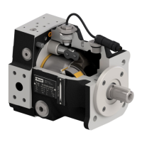
Electro hydraulic proportional controls version 45 for
axial piston pumps, PV series
Bulletin MSG30-3254-INST/UK
Installation and setup manual
The position of the control spool of the pressure
compensator is controlled by the pressure drop
across the pilot orifice Bp and by the compen-
sator spring. The nominal control pressure
dierence is factory-set to a value of 15 ± 1 bar.
As long as the pressure setting of the pilot
valve (in figures 5: proportional pressure valve
PVACRE***K**) is not yet reached, the control
valve spring keeps the control spool in the posi-
tion shown. The control port of the displacement
control valve is connected to the large servo
piston area and controls the position of the
servo piston.
The displacement control operates as described
in chapter 2. The adjustment of the control
pressure is done between the control spool and
control orifice.
When the set pressure of the pilot valve is
reached, this valve opens and control flow from
the pump outlet is passing the pilot orifice Bp
and the pressure pilot valve before returning
to the pump drain line. That creates a pressure
drop across pilot orifice Bp. If this pressure drop
reaches the 15 bar setting of the compensator,
the control spool of the pressure stage is in its
control position.
That leads to a reduction of the pump displace-
ment in order to keep the pump outlet pressure
constant. As the displacement control wants
to keep the pump at the set displacement the
proportional solenoid is powered with nominal
current. That connects the control port of the
displacement control valve with the pump case
(port T).
The control spool of the pressure stage now
controls the servo piston position by using
the control orifice B
D2
for pressure dividing.
Pressure control is achieved as with a stand-
ard remote compensator. It is mandatory, that
the displacement setting of the displacement
control stage is high enough, to cover the flow
requirements of the system, the pump and the
control valves to maintain the desired pressure.
The following valve is to be used with this mod-
ule: PVACRE***K**. Other valve models can
lead to instability problems or malfunction of
the control.
This valve is designed for a nominal pressure
of 350 bar. By using the MAX adjustment at the
control module, the input commend range can
easily be adjusted to any smaller nominal system
pressure. In this way also for these lower pres-
sures full resolution of the input command can
be achieved.
For basic adjustment of the control valves and
the displacement transducer see chapter 9. For
electrical connection and cable requirements
see chapter 12.
Note: Parker has decided for this design with
a separate hydraulic-mechanically operated
remote pressure compensator, which overrides
the proportional displacement control for three
reasons:
1. Piston pumps of the PV series have a large
servo piston. That oers several advantages.
On the other hand the servo piston has a high
flow demand for compensation. A hydraulic
mechanical pressure compensator – as used
here – can provide much higher control flows,
than a proportional directional control valve
used by other pump models, where this valve
also provides pressure control basing of the
signal of a pressure transducer.
2. The hydraulic-mechanical control valve
„senses“ a pressure peak in the system, as
the pressure acts direct on the control spool.
Depending on the actual system pressure very
high forces are available to operate the spool.
Therefore this control rarely will tend to stick
or malfunction, as proportional directional
control valves may do under contaminated fluid
conditions.
3. The pressure control using a proportional
pressure control valve to pilot it, does not require
a pressure sensor at the pump outlet. Never-
theless a closed loop pressure control can be
oered if required (see next chapter).
Function description UDR / UDK (old: UPR / UPK)