PVSG User Guide
7
3.1.1. Power control digital input connections
When connecting power control (wake up) inputs, note that
• e power control digital input is usually connected to the vehicle ignition, but it can be connected
to any power source in a system.
• To protect the harness that connects the PVSG to the ignition, place a fuse of 200 mA or higher in the
circuit that feeds the PVSG.
• When battery power (VBATT) is connected, and the power control digital input is inactive, the PVSG
will go into sleep mode.
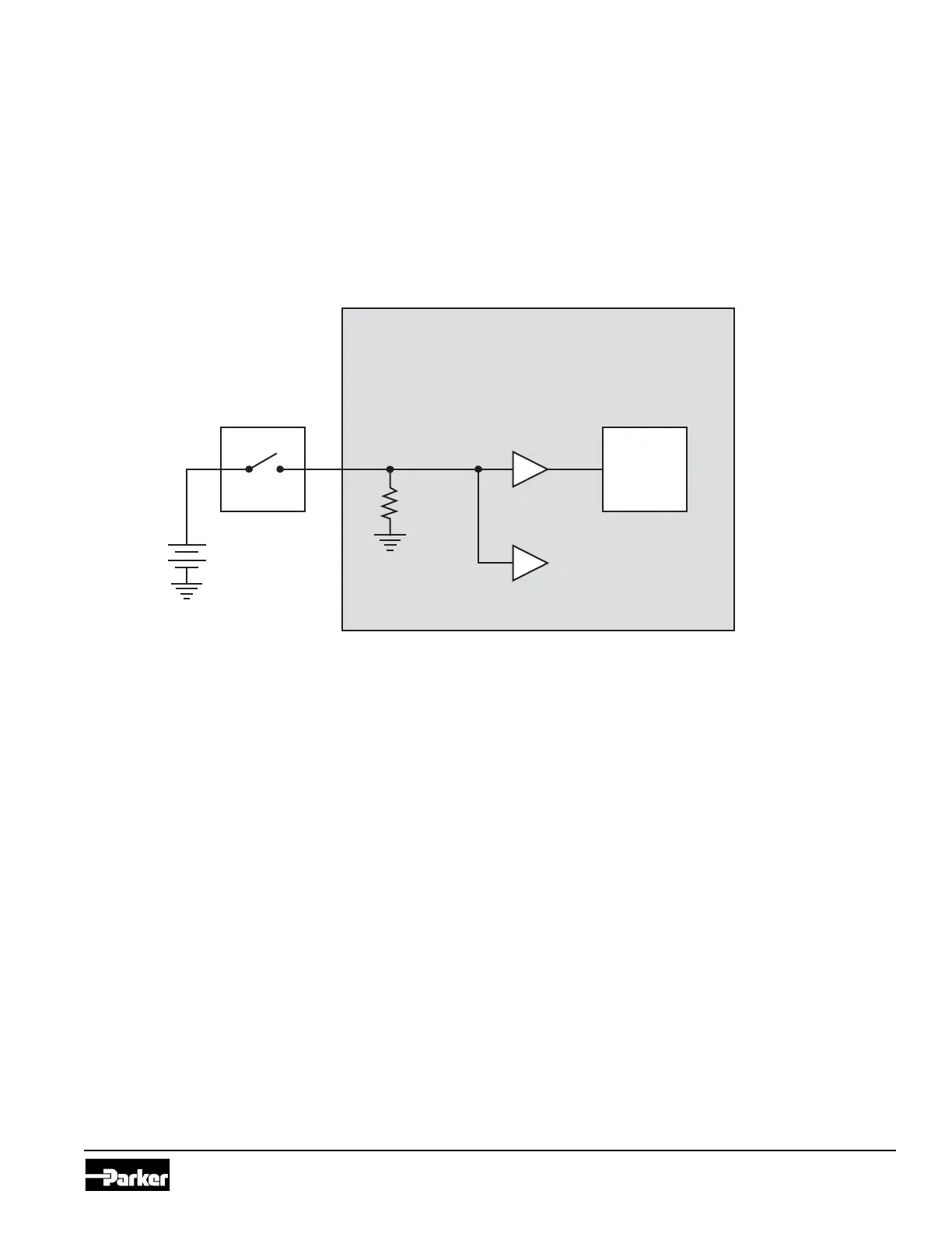
e following diagram shows a typical power control digital input connection:
Internal to product
Power Control Input
Power
Control
Pull-Down
Resistor
Battery
Application Switch
Figure 3.1. Power control digital input installation connections
3.1.2. Active-high digital input connections
A digital input is typically connected to a switch that is either open or closed.
• When an active-high switch is open, the pull-down resistor ensures that no voltage exists on the
input signal, which will be interpreted by the PVSG as inactive.
• When the switch is closed, the input is connected to battery voltage, which will be interpreted by the
PVSG as active.
For an input that is active-high
• It must be connected to battery power so that there is a battery connection when the state of the
input changes.
• e power provided to the digital switch connected to the input must be provided through a fuse in
the wire harness.