PVSG User Guide
12
6. Communication
e types of communication available to the PVSG family are Controller Area Network (CAN), Wi-Fi, USB
host/device, J1708, LIN, and Ethernet. e types and quantity of communication ports are dependent on
product version.
6.1. Controller area network
e PVSG has 5 Controller Area Network (CAN) communication port(s) available. e PVSG hardware
provides controller area network (CAN) communication according to the SAE J1939 specication,
making the PVSG compatible with any CAN-based protocol through software.
CAN communication is used to communicate the status of multiple modules that are connected to each
other in the same network.
6.1.1. CAN Capabilities
e CAN communicates information at a selectable rate from 125 kbps to 1000 kbps. Lack of regular
CAN communication is an indication that there is either a problem with a module in the network, or a
problem with the CAN bus.
CAN communication provides a feature called Wake on CAN, which is a way to provide power control to
the PVSG.
Wake on CAN provides a low-current sleep mode that turns on the PVSG when a CAN message is
received by the module.
It is not possible to lter messages that are used to turn on the PVSG using Wake on CAN. For this reason,
any message will turn on the PVSG. e application software must be written to determine how the PVSG
will behave when it is turned on.
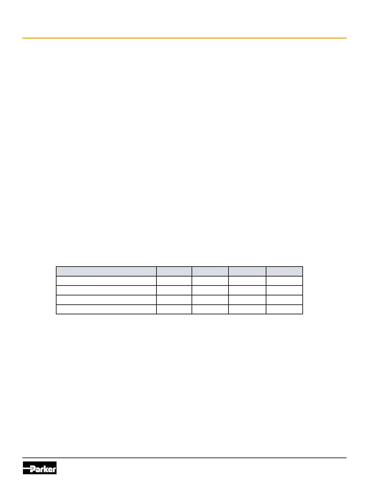
e following table provides specications for the CAN:
Item Min Nom Max Unit
Baud rate limitations (hardware) - - 1000 kbps
Baud rate limitations (software) 125 - 1000 kbps
Wake on CAN current draw - - 500 uA
Termination resistor 120 - - Ω
6.1.2. J1939 CAN Installation Connections
e CAN connection for the PVSG should conform to the J1939 standard. e J1939 standard is a robust
automotive specication that is a good CAN installation guideline even when the J1939 CAN protocol is
not being used.
For a list of J1939 connection considerations, refer to the SAE J1939 specications available through the
Society for Automotive Engineers. SAE J1939-11 covers the physical aspects of the CAN bus including
cable type, connector type, and cable lengths.
Note: e standard variant of the PVSG does not have a CAN termination resistor, which is based on the
assumption that the CAN bus is terminated in the harness.
e following lists the elements that are required for a J1939 CAN connection:
• CAN Cable: A shielded twisted-pair cable should be used when connecting multiple modules to
the CAN bus. e cable for the J1939 CAN bus has three wires: CAN High, CAN Low, and CAN
Shield (which connect to the corresponding CAN_HIGH, CAN_LOW, and CAN_SHIELD pins on the