PVSG User Guide
13
connector). When a module does not have a CAN_SHIELD pin, the CAN Shield should be connected
to an available ground terminal attached to the negative battery. e CAN cable must have an
impedance of 120 .
• e CAN cable is very susceptible to system noise; therefore, CAN shield must be connected as
follows:
a. Connect CAN Shield to the point of least electrical noise on the CAN bus.
b. Connect CAN Shield as close to the center of the CAN bus as possible.
c. Use the lowest impedance connection possible.
Note: Ground loops can damage electronic modules. e CAN Shield can only be grounded to one point
on the network. If grounded to multiple points, a ground loop may occur.
• CAN Connectors: Industry-approved CAN connectors are manufactured by ITT Cannon and
Deutsch, and come in either T or Y congurations.
• CAN Harness: e CAN harness is the main backbone cable that is used to connect the CAN network.
is cable cannot be longer than 40 meters and must have a 120 terminating resistor at each end.
e 120 terminating resistors eliminate bus reections and ensure proper idle-state voltage levels.
• CAN Stubs: e CAN stubs cannot be longer than 1 meter, and each stub should vary in length to
eliminate bus reections and ensure proper idle state voltage levels.
• Max Number of Modules in a System: e CAN bus can handle a maximum of 30 modules in a
system at one time.
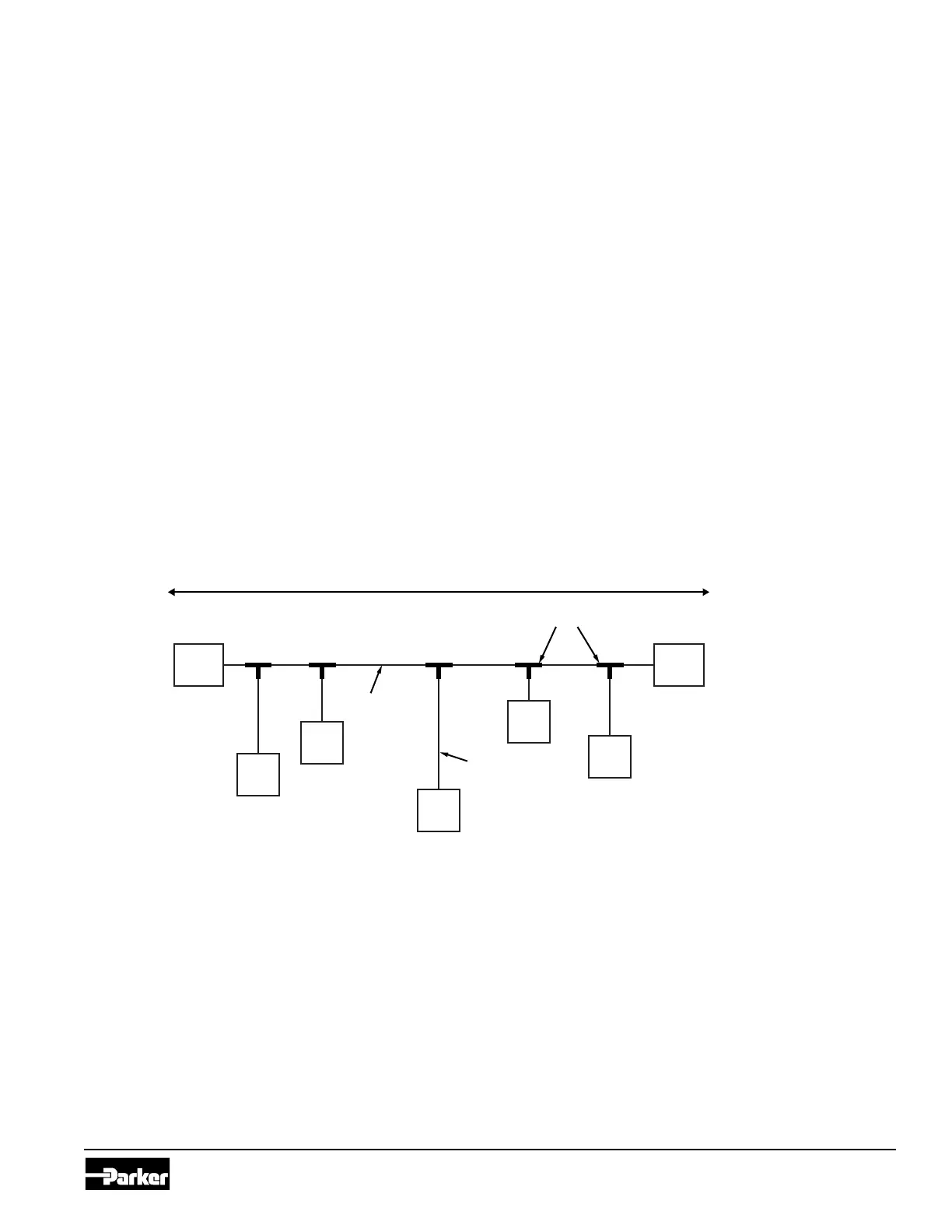
e following shows a typical CAN connection using the SAE J1939 standard:
120 ohm
Terminator
120 ohm
Terminator
Node
Node
Node
Node
Node
T connectors
Variable length
CAN stub (<1m)
(less than 40 meters long)
Figure 6.1. J1939 CAN connection