PVSG User Guide
3
2. Connectors and pin-outs
e PVSG has 2 Molex MX150 connectors that are keyed to prevent improper connection.
e mating connector for the PVSG, J1 connector is a 20 position MX150 key B (gray), and the mating
connector for the PVSG, J2 connector is a 16 position MX150 key A (black).
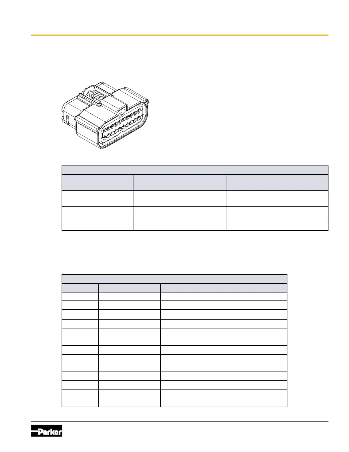
Figure 2.1. Molex MX150 connector example
Mating connector part numbers
Connector Molex part no. with CPA
locking clip
Molex part no. without CPA
locking clip
J1 connector (gray),
20-pin, key option B
334722007 334722002
J2 connector (black),
20-pin, key option A
334721606 334721601
Contacts 330013004 (16-20 awg gold) 330013004 (16-20 awg gold)
e pins in the Molex MX150 connectors are used for power, input, output, CAN, LIN, and J1708
communication channels, depending on version.
e following tables shows the pin-outs for the MX150 connectors:
J1 Connector Pinout
Pin I/O Name Function
1
INPUT2
Input2 (GPIO)
2
INPUT1
Input1 (GPIO)
3
CAN2_SHLD
CAN2 Shield
4
CAN2_L
CAN2 Low
5
CAN2_H
CAN2 High
6
CAN1_SHLD
CAN1 Shield
7
CAN1_L
CAN1 Low
8
CAN1_H
CAN1 High
9
GND
GND (Negative battery)
10
+VBATT
+VBATT (Positive battery)
11
CAN3_SHLD
CAN3 Shield
12
CAN3_H
CAN3 High
13
CAN3_L
CAN3 Low