PVSG User Guide
9
4. Outputs
e PVSG provides a switched battery (open source) digital output (OUTPUT1). is output includes
hardware short circuit protection if a short circuit fault is detected.
4.1. Output capabilities
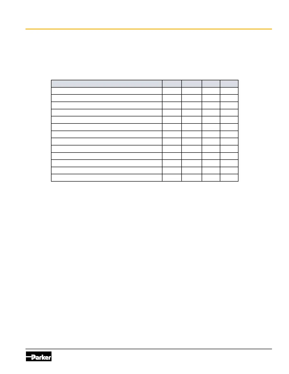
e following table provides specications for the high-side outputs:
Item MIN NOM MAX UNIT
Maximum output current 0 32 V
Output load current range 0 250 mA
Short circuit current limit
Output Resistance - w.r.t. ground: Output off 9.86
Output Resistance - w.r.t. VBATT: Output on 1 3
Output leakage current: Output off 20 uA
Output current, fault detection (Output off state) 4.5 mA
Output PWM frequency 20 Hz
Output duty cycle 50 %
Turn on delay, Off to On 500 us
Turn off delay, On to Off 500 us
Turn on/off slew rate 0.7 V/us
Output pin capacitance 10 nF
4.2. High-side output connection
When connecting the high-side output, note that
• High-side output circuitry is connected internally to battery power (VBATT).
• High-side output can provide switched battery power to any load type in a vehicle.
• High-side output can source up to 0.25 A max.
• High-side output have internal yback diodes, which are needed when driving inductive loads (the
yback diodes absorb electrical energy when the load is turned o).
Inductive loads will create an average current ow that moves out of the high-side output. When the
output is on, the current ows through the output driver, and when the output is o, the current ows
through the yback diode. A duty cycle of 50% will produce the worst case average current ow through
these two devices.
Note: If large inductive loads are used, and the high-side output is providing a continuous PWM signal,
the PWM peak current must not be greater than the specied continuous current for the output (in
continuous mode, the average current ow through the diode at 50% duty cycle is approximately equal to
½ the peak current).
When connecting high-side outputs, ensure you follow these best practices:
• High-side outputs should not be connected to loads that will draw currents greater than the
maximum peak current, or maximum continuous current.
• e grounds for the loads should be connected physically close to the PVSG power grounds.