PVSG User Guide
6
3. Inputs
e PVSG has 2 GPIO inputs.
• Both inputs are active high and able to be used as wake up (power control) inputs to activate the unit
or shut it down.
Damage to equipment! Do not connect inputs directly to unprotected inductive loads
such as solenoids or relay coils, as these can produce high voltage spikes that may
damage the CM0504. If an inductive load must be connected to an input, use a protective
diode or transorb.
3.1. Input capabilities
ere are 2 active high inputs (INPUT1 and INPUT2). is GPIO Type 1 input provides a xed input
detection threshold with xed pull down resistance.
e primary function of the inputs is to provide a wake on ignition feature as a digital input. e ‘Wake
Up’ functionality is software congurable.
A secondary function is to interface with switch sensors in an application.
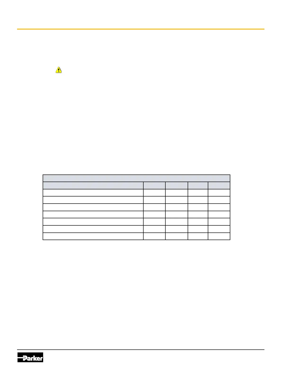
e following table provides specications for the inputs:
GPIO input Type 1 characteristics
Item Min Nom Max Unit
Input voltage range (non-operational) 0 32 V
Over voltage 36 V
Pull-up resistance open
Input resistance w.r.t. ground 10.11 kΩ
Negative going threshold 3.375 3.67 Vt
Positive going threshold 3.65 3.931 V
Filtering - hardware time constant 28 us