3. ELECTRICAL INSTALLATION 45
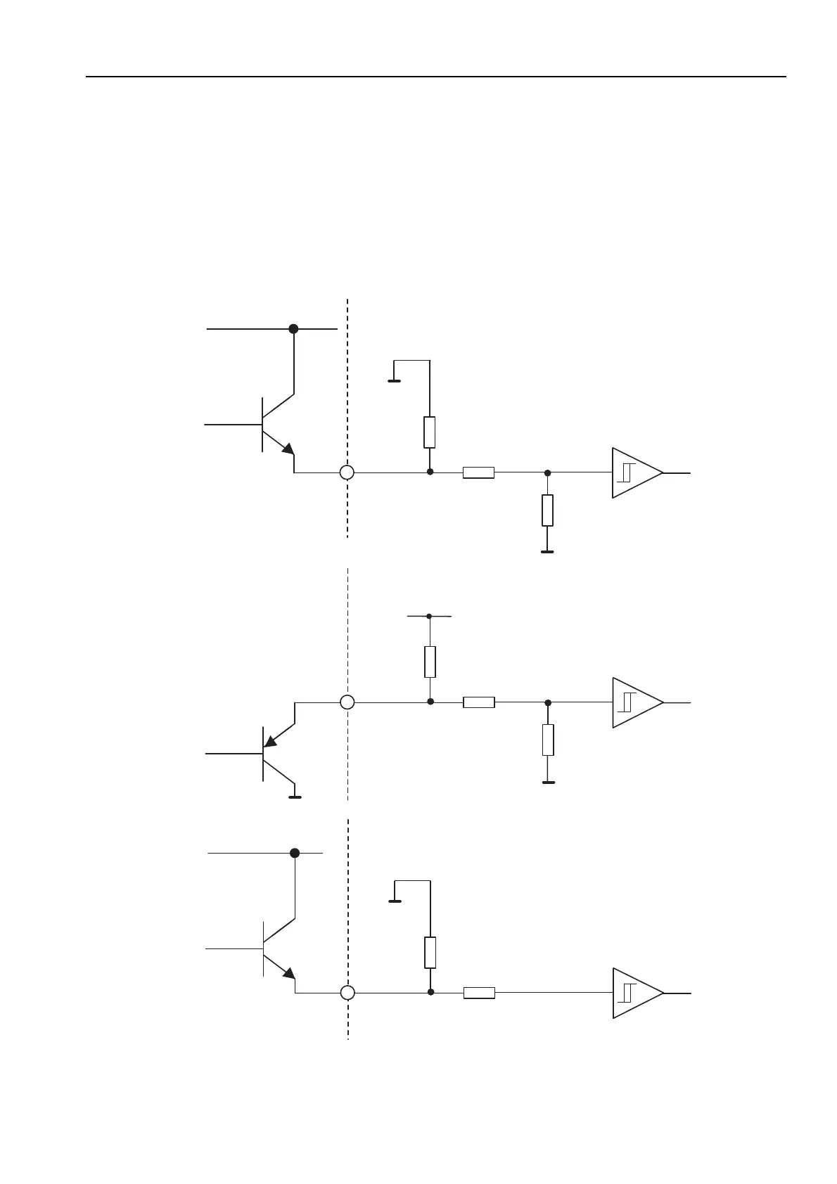
When driven from a high logic level 24V source, a logic ‘1’ (+24V logic) will engage the brake
and a logic ‘0’ (transistor off) will release the brake.
When driven from a high logic level 24V sink, a logic ‘1’ or a high impedance state (transistor
off) will engage the brake and an active pull-down to a logic ‘0’ (transistor on) will release the
brake.
Driving the input with a low level logic output, a logic ‘1’ (transistor on) will engage the brake
and logic ‘0’ (transistor off) will release the brake.
4K7
27K
82K
Drive
IC = 256
IC = 257
IC = 0
High logic
level source
High logic
level sink
0V
0V
4K7
27K
82K
Drive
24V
24V
0V
0V
4K7
82K
Drive
0V
Low logic
level source
5V
Figure 3-24. Brake Input Circuit
 Loading...