9 GB/IE/NI
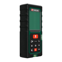
Description of parts
1
Hanging point
1a
Measurement starting edge
2
Display
3
Material switch STUD / AC WIRE /
METAL (wood / AC wire / metal)
4
MODE button
5
Stud button
6
READ button
7
M button (save)
8
Vial
9
Function switch LASER / DETECTOR /
DISTANCE
10
RM button (read memory)
11
Stud button
12
+ / =-button
13
Battery compartment
13a
Battery compartment cover
14
PUSH button
15
Laser beam opening / Laser sender
16
Laser receiver
LC Display (see fig. D):
17
Mode arrow
18
Battery symbol
19
High voltage warning symbol

 Loading...