EN
Disassembly
CAUTION: Always disconnect the fl ight battery from the model before
removing the propeller.
1. Remove the screw (A) and spinner (B) from the collet (G).
2. Remove the spinner nut (C), propeller (D), spinner backplate (E), backplate
(F) and collet (G) from the motor shaft (H). You will need a tool to turn the
spinner nut.
3. Remove the three screws (I) from the cowling (J). Carefully remove the
cowling from the fuselage. Paint may keep the cowling attached to the
fuselage.
4. Remove the four screws (K) from the motor mount (L) and the fuselage.
5. Disconnect the motor wires from the ESC wires.
6. Remove the four screws (M) and motor (N) from the motor mount.
Assembly
Assemble in reverse order.
• Correctly align and connect the motor wire colors with the ESC wires.
• The propeller size numbers (8.25 x 5.5) must face out from the motor for
correct propeller operation.
• A tool is required to tighten the spinner nut on the collet.
• Ensure the spinner is fully connected to the spinner back plate for safe
operation.
Not all wiring shown.
AB GDJHK
Service of Power Components
CE LMN
I
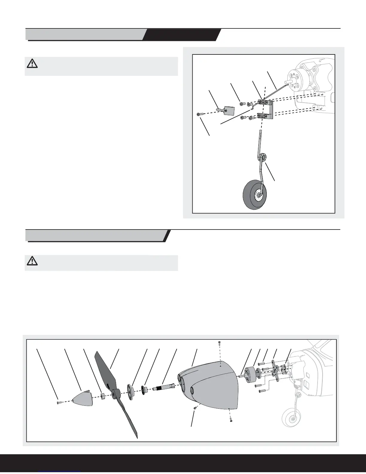
Removing the Nose Gear Nose Gear Service
Hard landings may damage the nose gear. Replace damaged parts as needed.
CAUTION: DO NOT handle the propeller while the fl ight battery is
connected to the ESC. Personal injury could result.
1. Remove the canopy from the model.
2. Disconnect the fl ight battery from the model.
3. Disconnect the steering linkage from the rudder servo arm.
4. Remove the propeller and cowling from the model (as shown in the
“Service of Power Components” section of this manual).
5. Loosen the nose gear screw (A) and remove the strut (B).
6. Remove the four screws (C) and steering arm retainer (D) from the fi rewall.
7. Pull the steering linkage (E) forward and remove the Z-bend end (F) of
the linkage from the steering arm (G).
Reassemble in reverse order.
NOTICE: Always make sure the steering linkage is adjusted correctly to ensure
the model steers straight when the rudder control is at neutral.
C
G
D
A
B
F
E
F
14