Rev. 007 Date 2010-01-13 CyFlow
®
space Instrument Operating Manual 12/26
Optical Flow Geometry
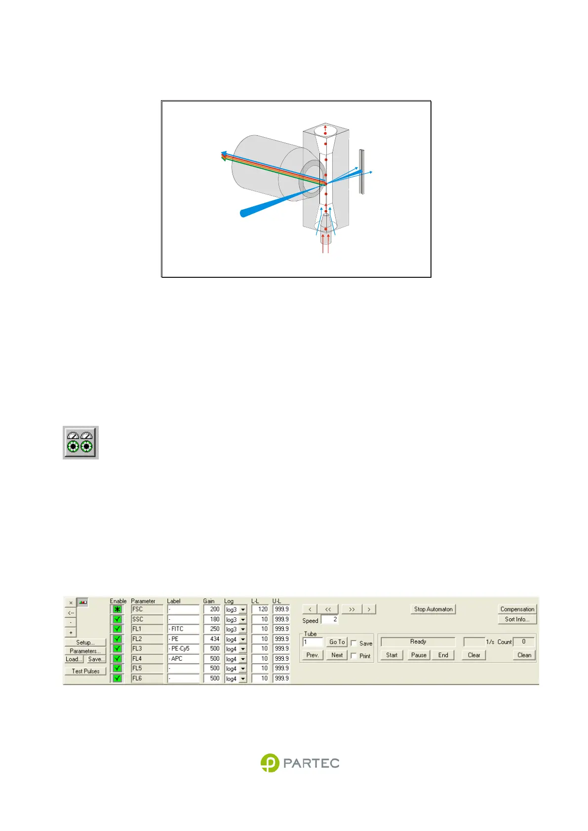
Fig. 3: Optical geometry at the flow cuvette (schematics).
Laser light is focused into the flow cell. Laser light scattered from the particles is detected in the forward
direction range (forward scatter). Side scatter and fluorescence light is collected by the objective at a right
angle.
Instrument Settings
Instrument settings are used to optimize the
CyFlow
®
space acquisition for the particles of
interest. The adjustments cover the gains of the
optical detectors, e.g. the photomultiplier high
voltages, the amplification mode (lin, 3 or 4
decade logarithmic), lower and upper level
thresholds and sample speeds. Instrument
settings can be once set up for a given application
and then be saved and reloaded for later use.
The following pages will describe the instrument
settings that can be made.
Please also refer to the software manual for
details on how to change the instrument settings.
Fig. 4: Multiparameter instrument settings box
sample
(hydrodynamic focusing)
laser beam
side scatter
fluorescence
forward scatter
sheath fluid
waste