7
force so giving control of penetraon.
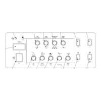
10) Inial Current/Hotstart This control is dual
funcon
in TIG mode it sets the start level for the welding
current as a percentage of the main welding current.
In MMA mode it allows adjustment of the welding
current surge on arc striking to give reliable arc
striking in all condions.
11) Gas Output connecon This is a 3/8 BSP
connecon for the gas output used in TIG welding.
12) Main amperage control. This control is used to
control the welding current in TIG and MMA modes.
13) Posive connecon This is used to connect the
electrode holder in MMA or the earth lead in TIG
welding.
14) Negave connecon. This is used to connect
the earth lead in MMA welding or the torch in TIG
welding.
15) control socket This is used to control the machine
remotely using a trigger or amperage control
5.0 Installaon
Read enre installaon secon before starng
installaon.
SAFETY PRECAUTIONS
• ELECTRIC SHOCK can kill.
• Only qualied personnel should perform this
installaon.
• Only personnel that have read and understood the
Operang Manual should install and operate this
equipment.
• Machine must be grounded per any naonal, local
or other applicable electrical regulaons.
• The power switch is to be in the OFF posion when
installing work cable and electrode cable and when
connecng other equipment.
5.1 Unpacking the Machine
Carefully remove the machine from the packaging,
we recommend you retain the packaging unl the
machine has been fully installed and tested incase it
has been damaged in transit and has to be returned to
the re-seller.
5.2 Locaon
Be sure to locate the welder according to the following
guidelines:
In areas, free from moisture and dust.
Ambient temperature between 0-40
0
C.
In areas, free from oil, steam and corrosive gases.
In areas, not subjected to abnormal vibraon or shock.
In areas not exposed to direct sunlight or rain.
Place at a distance of 12” (300 mm) or more from
walls or similar that could restrict natural airow for
cooling.
5.3 Input and grounding connecon
WARNING
Before starng the installaon, check that your
power supply is adequate for the voltage, amperage,
phase, and frequency specied on the Machine
nameplate.
Operate the welding power source from a single-
phase 50/60 Hz, AC power supply. The input voltage
must match one of the electrical input voltages shown
on the input data label on the unit nameplate. The
XTI-201 ACDC machine should only be used on 230V
supply. Refer to the specicaons table for voltage
tolerances.
Have a qualied electrician connect the input plug.
For long runs over 30m , larger copper wires should
be used. The green/yellow wire in the input cable
connects to the frame of the machine. This ensures
proper grounding of the machine when the machine
plug is inserted into the receptacle.
5.4 Output Polarity Connecons
Electrode polarity
MMA electrodes are generally connected to the ‘+’
terminal and the work lead to the ‘-‘terminal
But if in doubt consult the electrode manufacturer’s
literature.
IF TIG welding the torch should always be connected
to the ‘-’ terminal.
5.5 Torch installaon
MMA cable connecons
Connect electrode lead to posive terminal
TIG welding cable connecon
Connect the TIG torch to the - terminal
5.6 Work return lead connecon
MMA cable connecons
Connect work lead to negave terminal
TIG welding
Connect the work return lead to the + terminal
OPERATION