www.parweld.com
6
3.0
Technical Specications
Feature XTM 404S
Supply voltage 3 x 400 V, 50 Hz
Supply current, max. 19 A
Supply power 13,2 kVA
Fuse, slow 20 A
Welding range 40 – 350 A
No load voltage 17,0 – 36,0 V
Duty cycle:
100% - 260 A, 60% - 350 A, 35% - 300 A
Voltage steps 30
Welding wire Ø -
Protection IP 21
Insulation class H
Cooling AF
Dimensions (LxWxH) 865 x 495 x 690 mm
Weight 110 kg
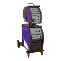
The XTM404S is a separate type machine with the wire feed unit
connected to the power supply by a 5m interconnecting cable.
For use with 3 phase 400V supply.
4.0 Description of Controls
1. On O switch. The machine is switched o when the light (4)
is o and the fan is not running.
2. Coarse Voltage selector switch. This switch is used to select
the require welding voltage each position of the switch
represents approximately 4V.
Do Not operate this switch while welding
3. Fine Voltage selector switch. This switch is used to select the
require welding voltage each position of the switch represents
approximately 0.5V.
Do Not operate this switch while welding
4. Mains input light This light illuminates when the mains power
is connected and the machine is switched on.
5. Fault light this light will illuminate when a fault or over
temperature condition has occurred. If this light illuminates
allow the machine to cool with the fan still running until it
extinguished. If the light does not go o when the power
source has cooled down then have the machine checked by a
qualied engineer.
6. Work return lead connection. This socket allows connection of
the work return lead to the front of the machine.
Note the XTM404S has 2 sockets for the work return lead
please refer below
7. Work return lead connection. High inductance connection, this
should be used when in spray transfer mode to give a more
stable arc. (Only tted to XTM404S)
8. Control Fuse
9. Function selector: 2-step, 4-step, Gas test
10. Wire speed adjustment
11. 2T 4T, when in the 2T position the torch trigger will have a
momentary operation ie the welding operation will start when
the rigger is depressed and stop when it is released. In the 4T
position a short press and release of the trigger will start the
welding operation and a short press and release with stop the
operation. The 4T mode is ideal for long welds as it reduces
operator fatigue. Gas purge. Allows gas to ow through the
welding torch and so allow checking of the gas ow before
starting the welding process.
12. Wire feed speed adjustment, controls the speed of wire
feeding from 0.8 to 24 m/min. Increasing the wire feed speed
also has the eect of increasing the welding current.
13. Burn back control aects the wire feed motor over run when
the trigger is released and can be adjusted to ensure that the
wire does not burn back onto the contact tip at the end of the
weld. (Increase to reduce wire stickout).
14. Soft start adjustment which controls the acceleration of the
wire feed motor when the arc starts to reduce spatter and give
a cleaner arc initiation.
15. Socket for the interconnection cable to link to the wire feeder.
16. Digital display for Voltage (displayed real time).
17. Torch connector The Euro connector provided the external
connection for the welding torch.
18. Mains input connection Input connection for the
pre-installed mains cable.
19. Water cooling connection from WF unit (optional)
20. Water cooling connection to WF unit (optional)
21. 24 V AC cooler or small power tools (optional).
22. Control circuit protection fuse. Auxiliary output (optional).
23. Welding power connection to connect to the
inter connect cable.
24. Welding Current Connector
25. Welding Power Input Connection.
26. Interconnection cable control socket input.
27. Shielding gas input connection 3/8 BSP male connection for
the shielding gas input.
28. Water cooling - to power source (optional)
29. Water cooling - from power source (optional)