www.parweld.co.uk
6
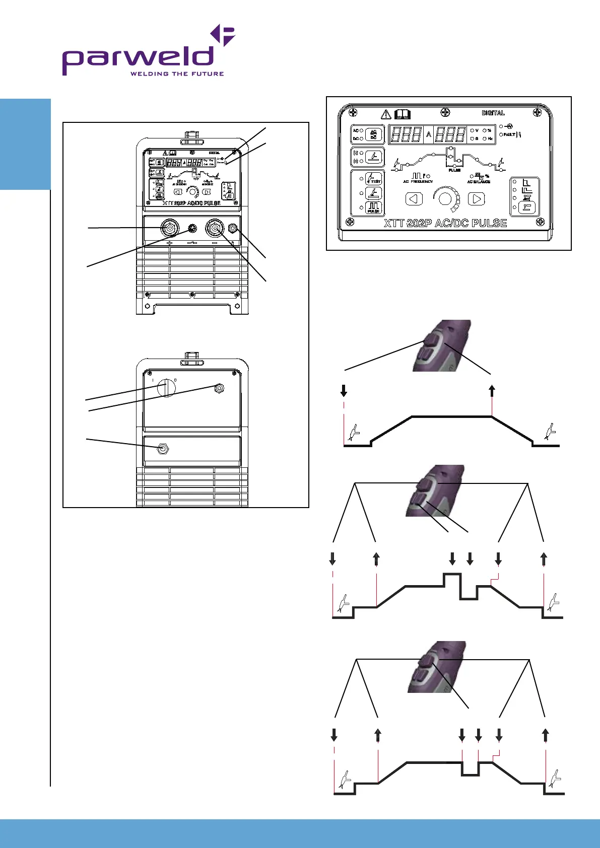
11) Switch mode (TIG), this toggles between 2 step and 4 step
operation of the torch trigger. In 2 step mode the trigger should be
pressed and held down until the end of the weld. In 4 step mode
(lower led) the trigger is pressed and released to start and pressed
and released to nish the weld. In order to TIG weld one of these
functions must be illuminated. Not all functions are available in 2T
mode.
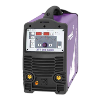
1) ON/OFF Switch for switching on or off the mains supply to the
machine. Note the output of the machine is permanently on in MMA
mode unless the on/off switch is in the off position.
2) Mains input Cable
3) Shielding Gas input connection
4) Power light This indicates mains power is applied to the machine
and that the machine is currently switched on when the light is
illuminated
5) Fault light This indicates a fault or over temperature condition
with the machine refer to the fault nding section for further
information
6) Gas Output connection
This is a 3/8" BSP connection for the gas output connection to the
welding torch (TIG welding)
7) Negative connection This is used to connect the electrode
holder in MMA or the earth return lead in TIG welding.
8) Positive connection This is used to connect the electrode holder
in MMA or the earth return lead in TIG welding.
9) control socket This is used to control the machine remotely using
a trigger or amperage control
10) Output power button. This button has 2 positions the top
position selects AC output in TIG or MMA mode and the bottom
position selects DC output in TIG or MMA mode as indicated by
the illuminated LED. Pressing the button toggles between the 2
positions.
CONTROLS
1
2
3
6
7
4
5
8
9
10
11
12
13
14
15
171819 19
Release
Press
Release
Initial
Current
Final
Current
Post Gas
Current
Adjustment
Pre Gas
Press
Step Current, 4T mode
Release Press
Release
Initial
Current
Final
Current
Post Gas
Pre Gas
Press
Tap
Button
Press
Pre Gas
Post Gas
Release
4T mode
2T mode
4.0 Description of Controls