www.parweld.co.uk
9
Type Application Colour
Ceriated 2% DC welding of mild
steel, Stainless
steel, Copper
AC welding
of aluminium,
magnesium and
their alloys
Grey
Zirconiated AC welding
of aluminium,
magnesium and
their alloys
White
Guide for selecting ller wire diameter
Filler wire diameter Current range
1/16” (1.6 mm) 20 - 90
3/32” (2.4 mm) 65 - 115
1/8” (3.2 mm) 100 - 165
3/16” (4.8 mm) 200 - 350
The ller wire diameter specied is a guide only, other diameter
wires may be used according to the welding application.
Shielding gas selection
Alloy Shielding gas
Aluminium & alloys Pure Argon
Carbon steel Pure Argon
Stainless steel Pure Argon
Nickel alloy Pure Argon
Copper Pure Argon
Titanium Pure Argon
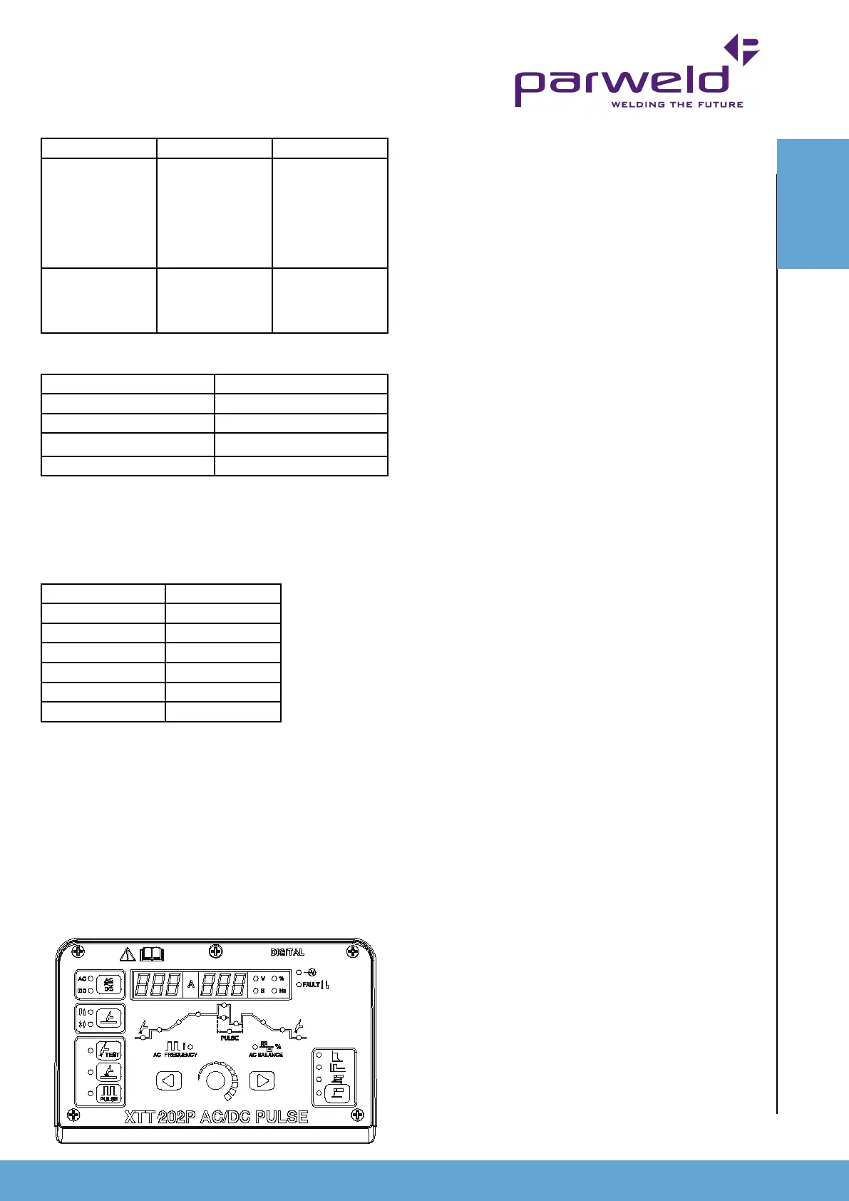
6.3 Machine setup for TIG Welding
6.3.1 DC TIG Welding (No Pulse)
Note:- shorting or dipping the electrode into the weld pool
for more than 1 second will cause the machine to reduce the
welding power to zero in order to protect the tungsten and
minimise contamination
1) Connect the torch to the - connection and the gas
hose to the gas outlet.
2) Connect the trigger control plug on the torch to the
trigger socket.
3) Connect the Earth lead to the + connection.
4) Set the process mode to 2T or 4T if you prefer a
latching trigger action. (Note in 4T position you must
press and release to start the process and press and
release again to stop the process) (A)
5) Select DC output (B)
6) Select HF start (C)
7) Using the toggle buttons (D) move the illuminated
LED to the gas pre-ow position (E)
8) Adjust the parameter value by rotating the knob (F)
This can be adjusted from 0.1 to 1.0 seconds. The
value is displayed on the Multifunction display (G)
9) Press the toggle button (D) to move the LED to
the initial current (H) This can be adjusted from 5 to
200Amps. The value is displayed on the Multifunction
display (G). Note this function only operates in 4T
switch mode
10) Press the toggle button (D) to move the LED to the
slope up time (I) This can be adjusted from 0 to 10s.
The value is displayed on the Multifunction display (G).
2s is a good initial setting.
11) Press the toggle button (D) to move the LED to the
main welding current (J) This can be adjusted from
5 to 200A. The value is displayed on the amperage
display (O). Refer to the TIG welding guide for a
recommended welding current.
12) Press the toggle button (D) to move the LED to the
slope down time (K) This can be adjusted from 0 to
10s. The value is displayed on the Multifunction display
(G). 2s is a good initial setting.
13) Press the toggle button (D) to move the LED to the
nal current (L) This can be adjusted from 5 to 200A.
The value is displayed on the Multifunction display (G).
Note this function only operates in 4T switch mode
14) Press the toggle button (D) to move the LED to the
Post Gas time (M) This can be adjusted from 0.1 to
10s. The value is displayed on the Multifunction display
(G). 3s is a good initial setting.
You are now ready to weld. The above settings are
a guide and you should adjust to suit the job you are
welding if you are unfamiliar with the machine try to
adjust only one parameter at a time so you become
familiar with its effect.
H
A
B
C
F
D
E
G
D
I
J
K
L
M
O
OPERATION
OPERATION