START-UP AND SETTING
With supply air shut off, set temperature adjusting knob at the
lowest temperature setting. Turn on supply air. The supply air
should be set at 2 psi above the maximum desired air signal. If
air is available at a higher pressure, install a pressure reducing
valve. No more than 1 to 2 pounds should show on the control air
gage (supplied with the T61 Pilot).
Gradually turn up temperature adjusting knob until rising loading
air pressure causes regulator to open. Continue raising temper-
ature setting in this fashion until desired
control temperature is reached.
The T61 Pilot is factory set so that 5
degrees variation above and below the
controlled temperature will cause the
loading air pressure to vary approx-
imately 8 pounds. The factory setting will
usually produce satisfactory control.
If closer control is desired, the sensitivity
of the T61 Pilot can be increased by
turning the sensitivity screw (7) clockwise.
This will cause the control temperatures
to move to a position below the set point.
This effect must then be corrected by
readjusting the temperature adjusting
knob (4).
Make these adjustments slowly, turning
the sensitivity screw no more than 1/8
turn and allow two or three minutes after
each adjustment for the system to settle
out. Practical range of adjustment of the
sensitivity screw is 1/2 turn from the
factory setting.
After final setting is reached, it may be
necessary to release the set screw in the
temperature adjusting knob and repo-
sition it so that the indicator is aligned
with the temperature being controlled. At
this point, the set screw is retightened.
If a hunt develops (a steadily swinging
temperature) when the sensitivity is
increased, the temperature pilot is being called on to function at
a setting finer than the installation will permit. At this point, factors
such as thermostat location, trapping and valve size should be
reexamined.
If the regulator swings immediately on startup and does not settle
out and decreasing the sensitivity by turning the sensitivity screw
(7) counterclockwise cannot be tolerated, the installation as a
whole should be restudied.
INSTALLATION
PLANNING
Locate the regulator in a horizontal pipe. Prevent water hammer
and erratic operation by providing a trap ahead of the regulator.
Avoid damaging effects of scale and dirt in pipelines by using a
strainer to protect the regulator. Provide a three valve bypass to
facilitate inspection of the regulator without interrupting service.
MAIN VALVE
Flush the main piping system thoroughly to clear it of welding
beads, scale, sand, etc. Mount main valve with diaphragm
chamber down and arrow on body pointing in the direction of
flow. Screwed end valve should be mounted in unions.
PILOT
Mount the pilot with the bulb projecting entirely into the liquid or
air being controlled. If the body is not in a horizontal position with
air gages on top, the set screw (5) on bottom of body nearest the
bulb may be loosened and body rotated to horizontal position.
Retighten the set screw.
Connect a reliable source of clean compressed air (not to exceed
32 psi) to the inlet of the pilot. The supply air should be set at 2
psi above the maximum desired air signal. If air is available at a
higher pressure, install a pressure reducing valve. CAUTION: Be
sure to blow out all lines before making final connections.
Connect pilot outlet to 1/4" tap on top of pressure pilot.
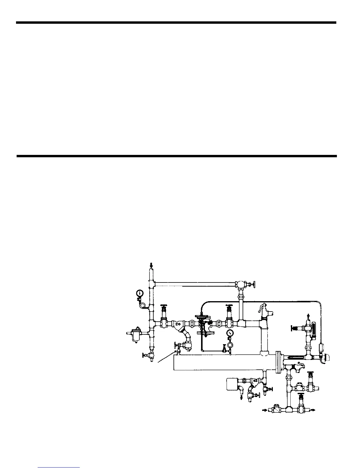
RECOMMENDED INSTALLATION
FIGURE 1
2
Angle Valve
Quick Vent
Air Valve &
Vacuum Breaker
Instantaneous Heater
Safety Valve
Drain
Initial
Pressure
Hot Water
Service
Pressure
Relief
Valve
F and T
Steam
Trap
From
Circulating Pump
Cold
Water
Supply
Control
Pipe
Type EAT61
Temperature
Regulator
Type T61
Temperature
Pilot
Steam
Trap
Gate
Valve
Gate
Valve
Check
Valve
Check
Valve
Gate
Valve
Strainer
Strainer
Condensate
 Loading...