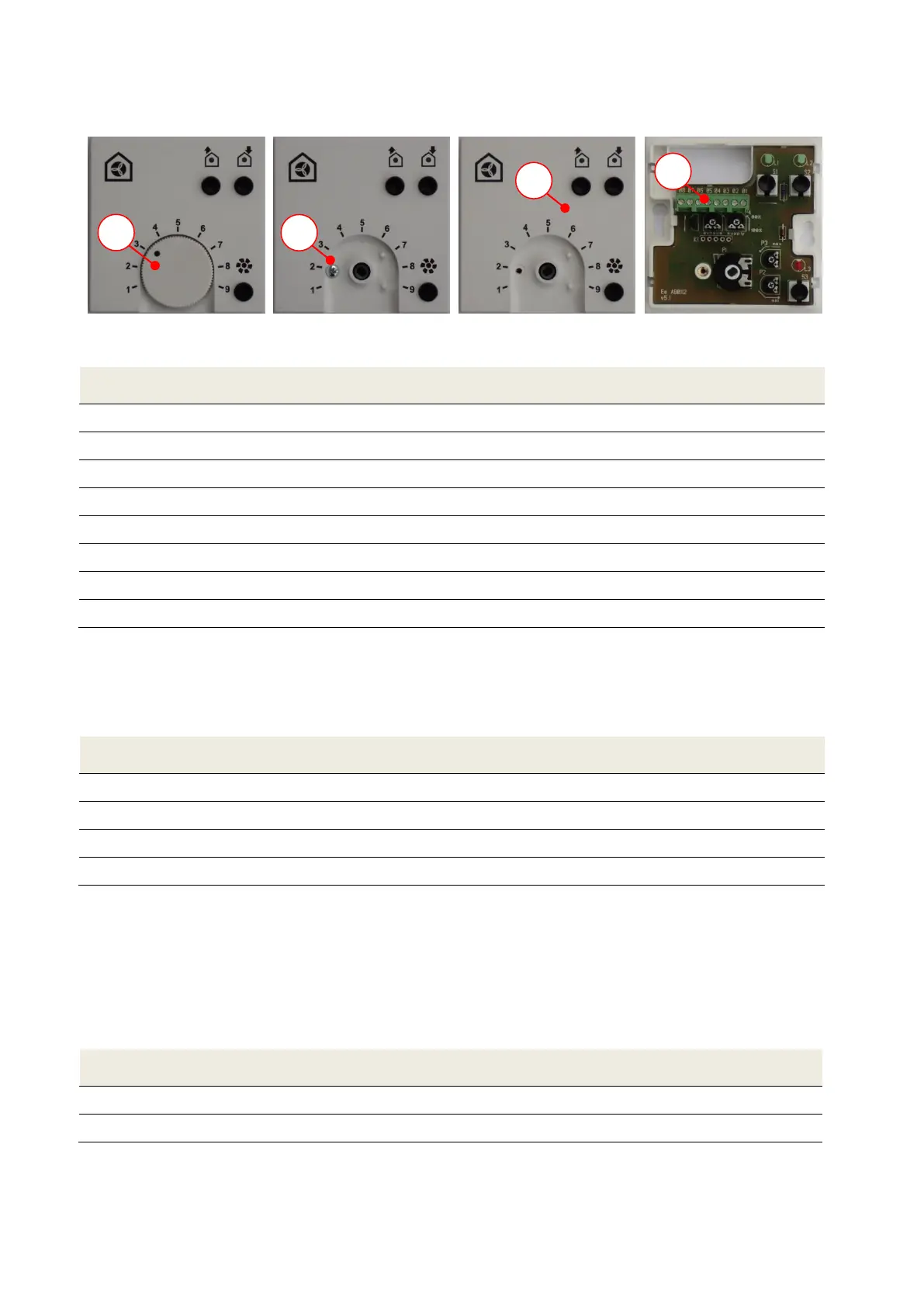
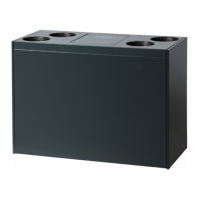
Open the control panel as follows:
3. Take top of control
panel off
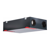
4. Access connection
terminal
Connection terminal control panel
U
s
(control voltage supply air fan)
U
e
(control voltage exhaust air fan)
Input external boost ventilation button
Input GND external boost ventilation button
Tab. 5: Terminal assignment connection terminal operating panel
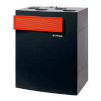
3.3.1.2 Connecting of the connection cable to the control unit
Connect the connection cable to the to the 4-pin screw terminal X0 according to Fehler! Verweisquelle
konnte nicht gefunden werden..
Terminal X0 control board
U
s
(control voltage supply air fan)
U
e
(control voltage exhaust air fan)
Tab. 6: Terminal assignment terminal X0 control unit
Connection of external boost ventilation switch 3.3.2
The boost ventilation mode can be activated by actuating one or more boost ventilation switches
connected in parallel. The switches which are usually installed in the design of the respectively used
switch range are triggered when the boost ventilation mode is activated. The potential-free connection
between button and connection terminal of the operating panel is made with an at least 2-strand cable
(recommendation: cable type J-Y(ST)Y 2x2x0.6).
Connection terminal operating panel
Wire cable boost ventilation switch
Tab. 7: Terminal assignment connection boost ventilation switch