Page 67
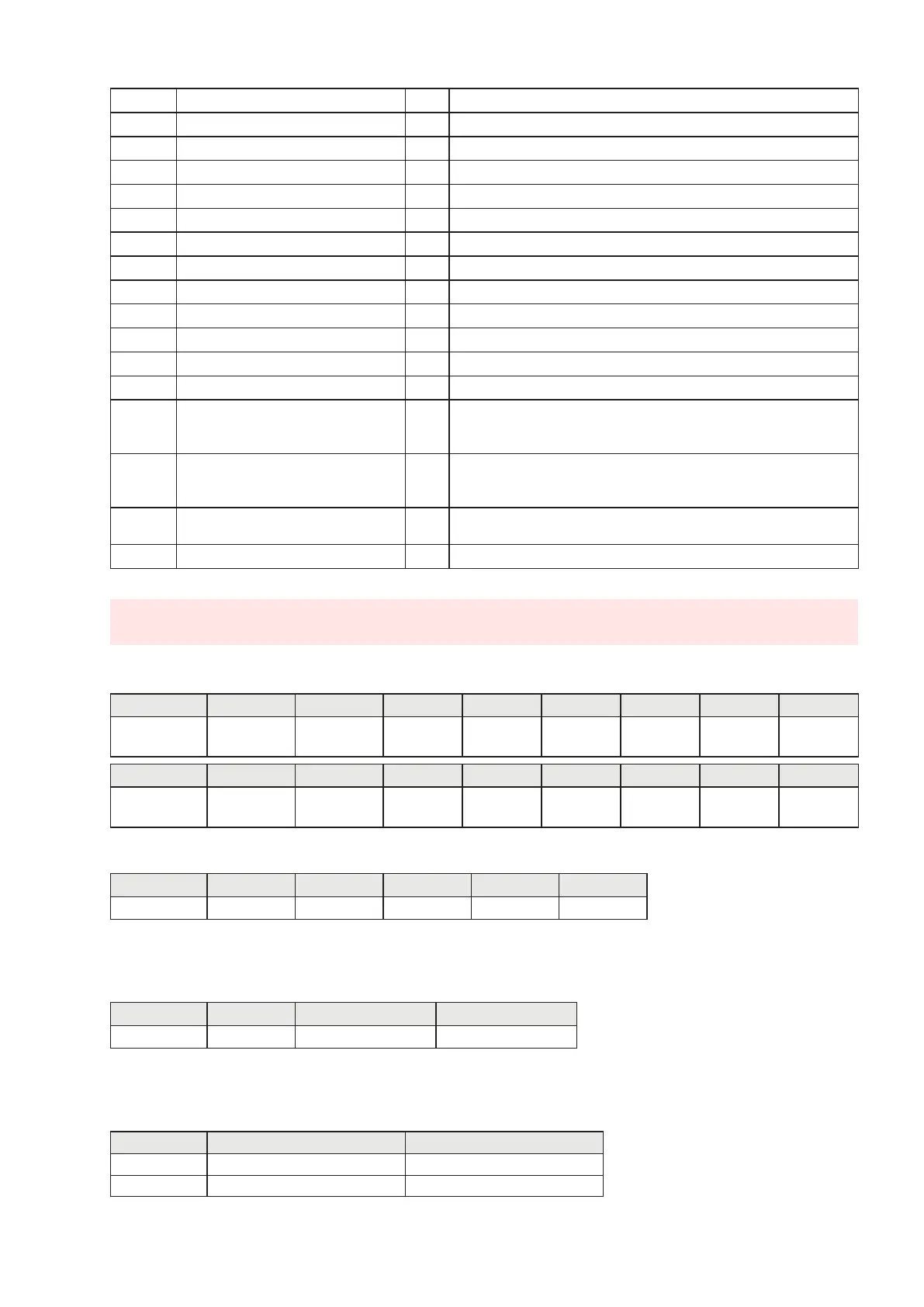
1410 Output mode 2—F unction R/W See correspondence on page 44
1411 Output mode 2— Logic R/W See correspondence on page 45
1412 Output mode 2— Polarity R/W See correspondence on page 45
1413 Output mode 2 — Stability R/W See correspondence on page 45
1414 Hysteresis output 2 R/W INT. value
1415 Timing output 2 R/W INT. value
1416 Delay output 2 R/W INT. value
1501 Analogue Tare (MSB R/W INT. value - Most significant word
1502 Analogue Tare (LSB) R/W INT. value - Less significant word
1503 Analogue Full Scale (MSB R/W INT. value - Most significant word
1504 Analogue Full Scale (LSB) R/W INT. value - Less significant word
1505 Analogue Output Mode R/W See correspondence on page 35
1506 Analogue Output Range R/W See correspondence on page 35
1507 Regulation of analogue zero R/W
INT. value Analogue output zero points, to end the regulation
procedure it is necessary to send the data storage command to
the permanent memory in the Command Register.
1508 Regulation of analogue full scale R/W
INT. value Analogue output full scale points, to end the regulation
procedure it is necessary to send the data storage command to
the permanent memory in the command register.
2000 Monitor register W
The programmed value is automatically copied in the Monitor
Register R (2100).
2100 Monitor register R
(*) These registers can only be modified in FREE mode or if in METRIC mode with a calibration
bridge enabled.
TABLE A - REGISTER STATUS CODING
BIT 15 14 13 12 11 10 9 8
Description Setup (***)
Weight
difference
Output 2 Output 1 Input 2 Input 1
Run
Backup
Hold
function
BIT 7 6 5 4 3 2 1 0
Description
Not
calibrated
Weight
error
Over-load
Under-
load
Tare
entered
Zero
band
Stable
weight
Zero
centre
TABLE B - KEYPAD LOCK CODING
BIT 15÷4 3 2 1 0
Description
Not used SET Key FUN Key 0 Key PRG Key
ATTENTION: the bits from 15 to 4 are not managed and are always equal to 0.
TABLE C - INPUTS/OUTPUTS CODING
BIT 15÷2 1 0
Description Not used IN/OUT 2 Active IN/OUT 1 Active
ATTENTION: the bits from 15 to 4 are not managed and are always equal to 0.
TABLE D - DECIMALS AND DIVISION VALUE CODING
ADDRESS DESCRIPTION ACCEPTED VALUES
1104 Division value 1 - 2 - 5 - 10 - 20 - 50
1105 Number of decimals 0 - 1 - 2 - 3 - 4


 To Next Page