Do you have a question about the Pavone Systems DAT 1400 and is the answer not in the manual?
Read manual before operating, follow instructions carefully, and keep for future use.
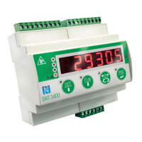
Describes the DAT 1400 weight transmitter, its features, and primary functions.
Lists various models of the DAT 1400 with different communication options.
Details power supply, dimensions, environmental specs, inputs/outputs, and communication interfaces.
Covers general data, overall dimensions, and electrical installation requirements for proper setup.
Details the instrument's power supply requirements and connection points.
Explains how to connect load cells, including wiring and jumper settings.
Describes the opto-isolated logic inputs and their activation.
Details the opto-isolated relay outputs and their capacity.
Configuration and usage of RS232 and RS485 serial communication ports.
Configuration and usage of the analog output in current or voltage.
Information on connecting the instrument to a PC via USB for configuration.
Overview of available fieldbus communication options.
Details on the RJ45 connector for Ethernet and its features.
Information on the Ethernet/IP protocol and its implementation.
Details on the Profinet interface and its features.
Information on the EtherCAT protocol and its connection method.
Locating and understanding the MAC address label for industrial Ethernet.
Details on connecting and using the Profibus DP fieldbus.
Information on connecting and configuring the Canopen fieldbus.
Describes the 6-digit display and status LEDs for instrument feedback.
Details on how the instrument enters and exits stand-by mode.
Explains the meaning of the logic output and weight status LEDs.
Explains the dual function of keys for navigation, selection, and data entry.
Instructions for locking and unlocking the instrument's keypad.
Procedures for safely exiting the setup and configuration menus.
Explains the display test on startup and normal operating mode display.
Lists common error codes and their meanings for troubleshooting operational issues.
How to toggle between gross and net weight display and interpret the NET LED.
Procedures for resetting weight and performing automatic tare functions for accurate measurements.
How the instrument memorizes and displays the peak value of the gross weight.
Procedures for testing serial ports, analog output, and input/output operations.
How to set and compare set-points to drive logic outputs.
Methods and conditions for acquiring and transmitting weight data.
Overview of setting parameters and accessing the setup menu for configuration.
How to change parameters when the instrument is in FREE operation mode.
Procedures for password-protected access in METRIC mode for calibration.
Setting the value of a single division in kilograms for weight resolution.
Configuring load cell capacity and sensitivity parameters for accurate weighing.
Conditions for accessing the calibration menu, requiring FREE or METRIC mode with password.
Using sample weights for zero and full-scale calibration.
Manually programming up to 5 linearisation points for improved accuracy.
Setting the analog output range (V/mA) and operation mode (NET, GROSS, PEAK).
Regulating analog output zero offset and setting the full-scale value.
Configuring baud rate, protocol, and frame type for the RS232 port.
Configuring output mode, protocol, and baud rate for the RS485 port.
Settings for Ethernet/IP, including IP address, subnet mask, and area dimensions.
Settings for Profinet/EtherCAT, including enabling, address, and area dimensions.
Assigning functions to input 1 and input 2 (e.g., Zero, Tare, Send).
Setting operating modes, polarity, stability, hysteresis, and timing for set-points.
Selecting between FREE and METRIC operation modes for the instrument.
Configuring weight stability criteria and auto-zero function on startup.
Adjusting filter settings for display refresh and output signal smoothing.
Configuring ADC speed for weight acquisition and number of readings for averaging.
Configuring standby idle time and keypad lock behavior.
Setting a password for menu access and enabling/disabling the peak function.
Setting up the datalogger for saving weight and I/O status.
Procedures for downloading log data via USB and deleting records.
Instructions for setting the instrument's internal date and time.
Menu for viewing access logs of authorized personnel in METRIC mode.
Procedure for consulting stored weighing data with identification codes in METRIC mode.
Details on ASCII data transmission protocols and string formats.
Commands and formats for master-slave communication using the serial interface.
Explains register addressing, data format, and error handling for Modbus RTU.
Lists and describes Modbus holding registers for instrument parameters.
Registers available in the input data area for fieldbus communication.
Registers available in the output data area for fieldbus communication.
Defines parameters and data structures for the Canopen communication profile.
Parameters related to the SDO server functionality in Canopen.
Configuration of PDO communication types and timing.
Mapping application objects to PDOs for data transfer.
Lists manufacturer-specific parameters with their index and sub-index.
Lists common problems, their causes, and recommended solutions for the instrument.
| Brand | Pavone Systems |
|---|---|
| Model | DAT 1400 |
| Category | Transmitter |
| Language | English |