EXC-
EXC+
SENSE+
SENSE-
SIG-
SIG+
SHIELD
10
18
+
-
+24 Vdc
0 Vdc
19
24
DAT 1400
FIELDBUS
SENSE-
SENSE+
SIGN-
SIGN+
C OUT
S.GND
Ana-
OUT2
C IN
EXC-
EXC+
OUT1
mA+
IN2
IN1
RXD
TXD
SHD
24V
V+
15
16
11
14
13
12
21
20
19
22
23
10
1
2
3
5
6
7
8
9
+
-
4
+24V
+EXC
-EXC
+SGN
-SGN
SHD
+EXC
-EXC
+SGN
-SGN
SHD
+EXC
-EXC
+SGN
-SGN
SHD
+EXC
-EXC
+SGN
-SGN
SHD
25 PIN CONNECTOR
+SGN
-EXC
+EXC
-SGN
+SNS
-SNS
+EXC
-EXC
+SGN
-SGN
+EXC
-EXC
+SGN
-SGN
+EXC
-EXC
+SGN
-SGN
+EXC
-EXC
+SGN
-SGN
SHD
SHD
SHD
SHD
SHD
2
3
6
1
5
4
7
1
2
3
4
5
1
2
3
4
5
1
2
3
4
5
1
2
3
4
5
J-BOX CGS4-C
Page 7
POWER SUPPLY OF THE INSTRUMENT
The instrument is powered via terminals 22 and 23. The power cord
must be channelled separately from the other cables.
The instrument is in insulation class II (double insulation) and there
is no ground terminal provided, which is however necessary to
connect the cable shields.
Make sure you have a valid ground connection.
Power supply voltage: 12÷24 Vcc ±15%, max 5W
LOAD CELL(S) CONNECTIONS
The cable of the cell(s) must be channelled separately, and not with
other cables.
A maximum of 8 load cells of 350 ohm can be connected to the
instrument in parallel. The supply voltage of the cells is 5 Vdc and
has temporary short circuit protection.
The measuring range of the instrument permits the use of load cells
with a sensitivity of up to 3.9 mV/V.
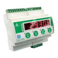
The cable of the load cells must be connected to terminals 11-18.
In the case of a 4-wire load cell cable, jumper the terminals 11 to
14and 12 to 13.
Connect the cell cable shield to terminal 10.
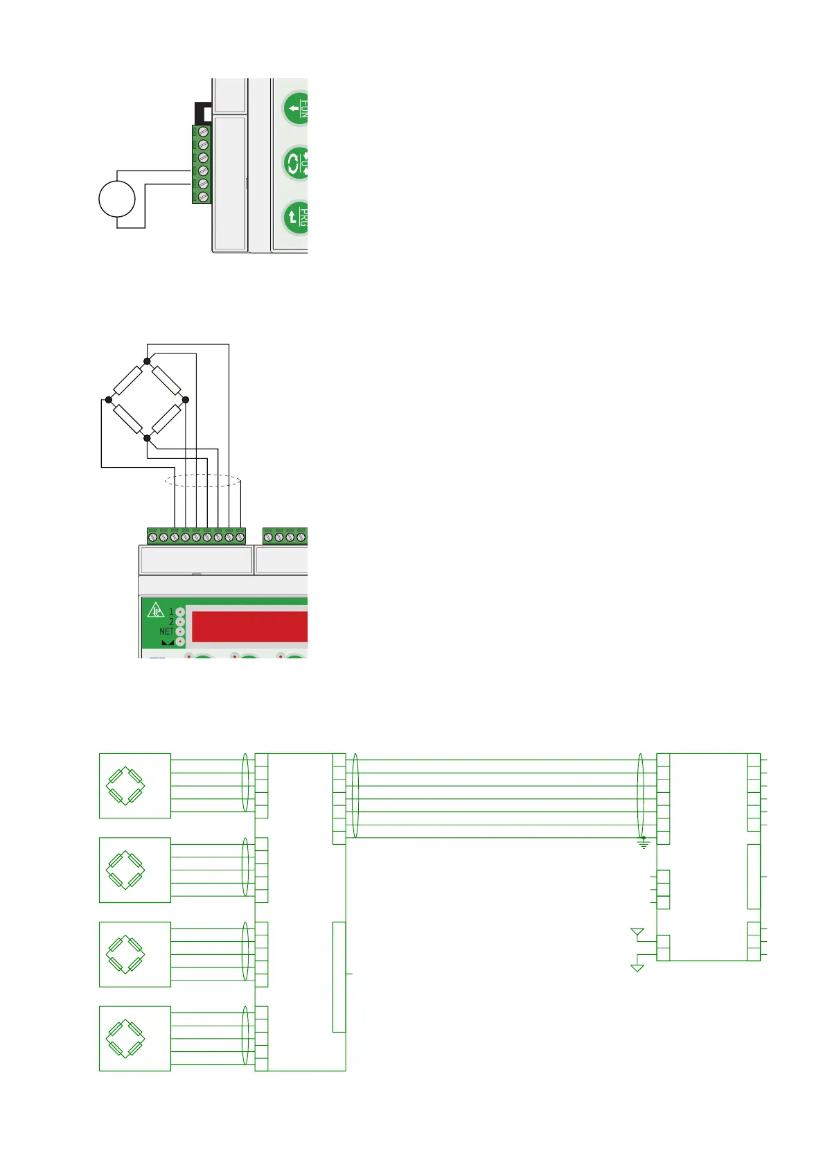
In the case of two or more load cells, use special junctionboxes
(CEM4/C or CSG4/C). The connection of these is shown below.